Circulating Fluidized Bed (CFB) boilers have become a preferred technology for industrial power generation and steam production, especially when using low-grade fuels like coal, biomass, or waste-derived fuels. However, their complex design and operation can be challenging to understand, making it difficult for users to optimize efficiency, ensure proper maintenance, or meet emission standards. Identifying and understanding the key components of a CFB boiler is essential for ensuring stable combustion, fuel flexibility, and environmental compliance.
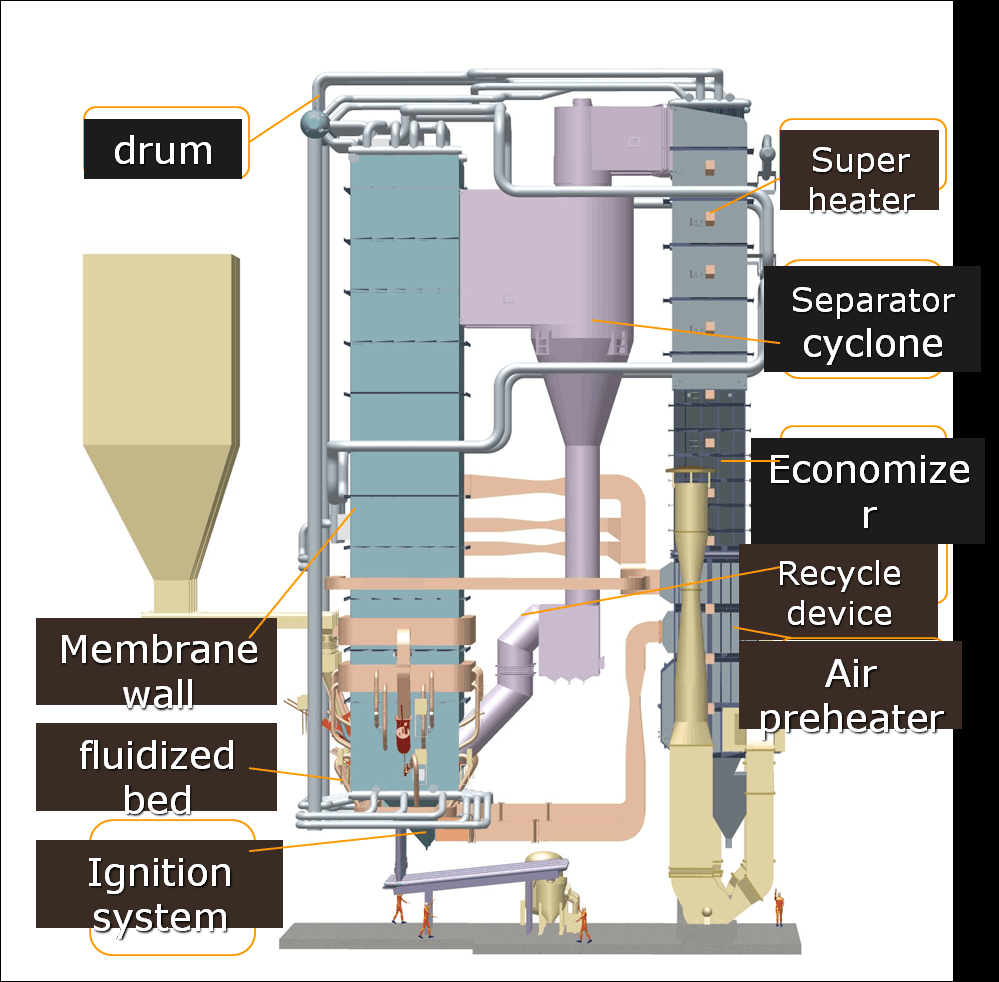
The key components of a circulating fluidized bed boiler include the combustion chamber (furnace), air distributor, cyclone separator, return loop system, heat exchangers (superheater, economizer, etc.), and control system. These components work together to enable continuous circulation of fuel and bed material, achieve uniform temperature distribution, and ensure efficient heat transfer. CFB boilers are designed for low-emission, high-efficiency performance with diverse fuels.
Understanding each component’s role in this integrated system will help ensure reliable performance, extended equipment lifespan, and reduced operational costs.
What is the function of the combustion chamber in a CFB boiler?
In industrial power generation, the combustion chamber is the core of any boiler system, and this holds especially true in a Circulating Fluidized Bed (CFB) boiler. The performance, fuel flexibility, and emissions control of a CFB boiler all depend on what happens inside its combustion chamber. But without understanding the dynamics within this space, operators may struggle with fuel conversion efficiency, temperature stability, and emission compliance. Ineffective combustion can lead to unburned fuel, operational instability, and increased maintenance. This article explores the combustion chamber’s critical role in CFB boilers, explaining how it enables efficient fuel burning, reduced emissions, and long-term reliability.
The combustion chamber in a Circulating Fluidized Bed (CFB) boiler functions as the primary zone where fuel combustion occurs in a turbulent environment of fluidized particles. It is designed to maintain a uniform high-temperature region (typically 800–900°C) using fluidized bed technology, where crushed solid fuels like coal, biomass, or waste materials are suspended and burned efficiently with high turbulence. This chamber ensures excellent fuel-air mixing, long residence time for complete combustion, and effective heat transfer to water walls, while also supporting in-situ emission control such as sulfur capture.
Understanding the design and operation of the combustion chamber is essential for plant engineers and operators aiming to maximize efficiency, reduce emissions, and ensure stable boiler output. Let’s explore the mechanics and advantages of this central CFB component in depth.
The Combustion Process in a CFB Boiler Combustion Chamber
Unlike traditional boilers where combustion happens on a grate or in a flame envelope, CFB boilers rely on fluidization, where fuel particles and bed materials like sand or limestone are suspended in an upward flow of air. Here’s how the combustion process unfolds:
| Step | Description |
|---|---|
| 1. Fuel and Bed Material Injection | Crushed fuel (coal, biomass, RDF) and inert bed materials (e.g., sand or dolomite) are fed into the combustion chamber. |
| 2. Primary Air Distribution | Air is blown from the bottom of the chamber through nozzles to fluidize the bed, creating a churning, turbulent environment. |
| 3. Ignition and Combustion | The air-fuel mixture ignites and burns within the fluidized bed. The high turbulence ensures uniform temperature and rapid combustion. |
| 4. Gas-Solid Separation | Fine particles are carried upwards and separated by cyclones. Unburned solids are returned to the chamber for further combustion. |
| 5. Heat Transfer | Heat is transferred from the bed and gases to the water walls lining the chamber, producing steam. |
Cross-Sectional Design and Key Zones of the CFB Combustion Chamber
The combustion chamber is typically a tall, rectangular enclosure lined with water-cooled membrane walls. It consists of several operational zones:
| Zone | Function |
|---|---|
| Lower Dense Bed Zone | Most of the solid fuel combustion and sulfur capture occurs here. Fluidization is most intense. |
| Freeboard (Dilute Phase) | Carries entrained particles and combustion gases upward to the cyclone separators. Partial combustion may continue here. |
| Cyclone and Return Loop | Captures entrained particles and recirculates them to the dense bed, improving fuel burnout and reducing waste. |
Advantages of the CFB Combustion Chamber Design
1. Enhanced Fuel Flexibility
The fluidized bed allows for low-grade fuels, biomass, petroleum coke, and waste materials to be burned efficiently without major design changes.
2. Stable Combustion Temperature
Unlike pulverized coal boilers, where flame temperature can spike to over 1300°C, CFB chambers operate at a uniform 850–900°C. This:
Reduces thermal NOx formation
Protects boiler materials from heat stress
Enhances limestone-based sulfur capture
3. Effective Emissions Control
The chamber enables in-situ desulfurization by injecting limestone directly into the bed. The calcium in limestone reacts with SO₂ to form solid calcium sulfate (CaSO₄).
4. Efficient Fuel Utilization
Long particle residence times (due to recirculation) and thorough mixing ensure near-complete combustion. Carbon burnout > 99% is typically achieved.
| Performance Metric | CFB Combustion Chamber |
|---|---|
| Combustion Efficiency | 95–98% |
| Carbon Burnout Rate | >99% |
| SO₂ Capture Efficiency | 85–95% with limestone |
| Operating Temperature | 800–900°C |
| NOx Emission | < 200 mg/Nm³ without special burners |
Real-Time Process Control in the Combustion Chamber
Modern CFB combustion chambers are monitored and optimized using:
Temperature sensors across height levels to detect hot spots or underburning.
Pressure differential transmitters to track fluidization stability.
Oxygen analyzers to maintain ideal excess air conditions.
Bed height monitors to control fuel and bed material feed.
These controls feed into Distributed Control Systems (DCS) for continuous optimization and early fault detection.
Practical Challenges and Solutions
While CFB combustion chambers are robust, they must be properly maintained to avoid issues like:
Agglomeration of bed particles: Managed by maintaining proper temperature and limestone quality.
Erosion of water walls: Minimized through special wear-resistant coatings or refractories.
Start-up delays: Addressed by fluidized bed pre-heaters or auxiliary burners.
| Challenge | Mitigation Strategy |
|---|---|
| Bed material clumping | Use bed additives, control moisture |
| Wall erosion | Use membrane walls with cladding |
| Incomplete combustion | Optimize primary/secondary air ratio |
Case Study: Biomass-Coal Co-Firing in a CFB Boiler
A 150 MW CFB power plant in Poland co-fired 40% biomass with 60% coal in its combustion chamber. Thanks to the chamber’s uniform temperature and high turbulence:
SO₂ emissions were reduced by 70% without external scrubbers.
NOx remained below 150 mg/Nm³.
Ash content and bed pressure were maintained despite fuel variability.
This highlights the chamber’s adaptability and environmental advantages.
Summary of Key Benefits
| Feature | Benefit |
|---|---|
| Uniform combustion zone | Stable heat generation and lower NOx |
| Particle recirculation | High fuel burnout and low ash loss |
| In-bed desulfurization | Reduced need for external scrubbers |
| Fuel flexibility | Biomass, RDF, and high-ash coals can be used |
| Scalability | Suitable for units from 20 to 600+ MW |
The combustion chamber of a CFB boiler is not just a burning space—it’s a smart, multi-functional zone that ensures efficiency, environmental performance, and operational resilience. Its design and operation are central to the success of any fluidized bed combustion system, making it a key focus for engineers, suppliers, and plant operators worldwide.
How does the air distributor impact fluidization and combustion efficiency?
In a Circulating Fluidized Bed (CFB) boiler, maintaining uniform fluidization is crucial for effective combustion, fuel efficiency, and emissions control. However, uneven air flow or poor distributor design can lead to defluidization, hot spots, unburned fuel, or even bed collapse—all of which compromise boiler efficiency and safety. The air distributor lies at the very heart of this dynamic, regulating how primary air enters the combustion chamber and interacts with the bed material and fuel. This article explains the critical function of the air distributor and how it directly affects combustion dynamics and boiler performance.
The air distributor in a CFB boiler plays a vital role in achieving uniform fluidization by introducing primary air evenly into the combustion chamber through a perforated plate or nozzle grid. This controlled airflow suspends the bed material and fuel particles, ensuring intense mixing, stable combustion temperatures, complete fuel burnout, and in-situ emission control. A well-designed air distributor prevents channeling, defluidization, and erosion, thereby improving combustion efficiency and operational reliability.
Understanding how the air distributor functions allows operators and engineers to fine-tune fluidization dynamics, adapt to different fuels, and prevent costly shutdowns. Let’s dive into its construction, performance impact, and best design practices.
Structure and Function of the Air Distributor
The air distributor is typically located at the bottom of the CFB combustion chamber and comprises a pressurized plenum, a distribution plate or grid, and multiple nozzles or orifices.
| Component | Function |
|---|---|
| Air Plenum Chamber | Receives pressurized primary air from forced draft fans and distributes it to the nozzles. |
| Distributor Plate/Grid | A flat or conical plate with uniformly spaced nozzles or holes that allows air to flow upward. |
| Nozzles or Air Caps | Ensure even pressure drop and air velocity; designed to prevent clogging by bed material. |
The primary air flow through the distributor achieves fluidization—a state where the solid bed behaves like a boiling liquid. This turbulence ensures continuous particle suspension, rapid mixing, and complete combustion.
Effects on Fluidization Quality
Proper air distribution ensures that:
No dead zones exist where fuel or bed material accumulates.
Turbulent mixing occurs uniformly across the entire combustion bed.
High residence time is maintained for both fuel and bed particles.
Temperature uniformity is preserved across the bed cross-section.
| Parameter | With Optimized Air Distributor | With Poor Air Distribution |
|---|---|---|
| Fluidization | Uniform | Channeling or dead zones |
| Combustion Temperature | 850–900°C, stable | Hot/cold spots |
| Carbon Burnout | >99% | Incomplete combustion |
| Bed Pressure Drop | 7–12 kPa (balanced) | Fluctuating or unbalanced |
| Ash Quality | Fine, low carbon content | High unburned carbon |
Impact on Combustion Efficiency
Combustion efficiency in a CFB boiler is closely linked to how well the air distributor suspends and mixes particles:
Improved Oxygen Distribution: Uniform air distribution ensures that all fuel particles receive adequate oxygen for complete combustion.
Optimized Fuel-Air Ratio: Prevents excess air and its associated heat losses while avoiding localized oxygen depletion.
Reduced Emissions: Proper fluidization minimizes CO, NOₓ, and unburned hydrocarbons by maintaining a consistent temperature and oxygen profile.
Graph: Carbon Burnout vs Air Distribution Uniformity
Carbon Burnout (%)
|
|                     ● Optimal Distributor
|                     ●
|                    ●
|                  ●
|                ●
|             ●
|         ●
| Poor Distributor
|__________________________
            Uniformity of Air Distribution
Design Considerations for Effective Air Distribution
To achieve optimal combustion, several factors must be considered during the design of the air distributor:
1. Nozzle Density and Layout
High nozzle density ensures fine control of airflow and avoids short-circuiting.
Patterns (hexagonal, square) must ensure symmetrical air supply across the bed.
2. Pressure Drop Design
Designed to maintain a uniform bed pressure drop between 7–12 kPa.
Helps overcome the resistance of bed particles and prevents backflow.
3. Nozzle Design
Nozzles should resist erosion, clogging, and corrosion.
Multi-hole or swirl-type designs promote localized turbulence and enhance mixing.
4. Plenum Compartmentalization
Dividing the plenum into zones allows staged air distribution.
Enables fuel-staged combustion to reduce NOₓ emissions.
5. Maintenance Access
Distributors must be accessible for nozzle cleaning and replacement.
Erosion-prone areas can be lined with high-chrome or ceramic coatings.
Operational Strategies to Maintain Air Distributor Performance
| Practice | Benefit |
|---|---|
| Regular inspection | Detect nozzle wear, blockage, or erosion. |
| Bed material screening | Prevents oversized particles from clogging nozzles. |
| Plenum pressure monitoring | Indicates distributor health and fluidization quality. |
| Air flow balancing | Ensures each nozzle zone receives proportional flow. |
Case Example: Air Distributor Upgrade in a 200 MW CFB Plant
A CFB power plant in India experienced combustion instability due to poor air distribution. By retrofitting with a multi-zone air distributor featuring conical nozzles and ceramic linings, the plant achieved:
8% increase in fuel efficiency
Reduction in unburned carbon in fly ash from 7% to 2%
25% improvement in combustion stability
Decrease in bed agglomeration incidents
Summary: Why the Air Distributor is Crucial
| Function | Result |
|---|---|
| Even air supply | Uniform fluidization and stable combustion |
| Controlled turbulence | Improved fuel-air contact and burnout |
| Resistance to erosion | Long-term reliability |
| Integration with controls | Enables responsive load-following |
The air distributor is far more than just a set of holes at the bottom of a CFB boiler—it is the engine of fluidization, combustion efficiency, and operational resilience. Ensuring its proper design, installation, and maintenance is essential for any CFB system seeking consistent, clean, and efficient performance.
What role does the cyclone separator play in material recirculation?
In Circulating Fluidized Bed (CFB) boilers, maintaining high combustion efficiency, uniform heat transfer, and effective emissions control all depend on the continuous movement and recirculation of bed materials. Without a proper mechanism to recover and return entrained solids, performance degrades significantly. The cyclone separator plays a pivotal role in separating solid particles from flue gases and recirculating them back into the furnace, thus ensuring stable bed inventory, better fuel conversion, and low emissions. In this article, we explore how the cyclone separator works and why it is indispensable in CFB boiler operation.
The cyclone separator in a CFB boiler captures solid particles carried with the flue gas from the combustion chamber and returns them to the furnace, enabling continuous recirculation of bed material. It uses centrifugal force to separate solids from gases, ensuring high collection efficiency, enhanced combustion, fuel flexibility, and reduced particulate emissions. This recirculation stabilizes bed dynamics, improves heat retention, and maximizes fuel burnout.
Understanding the function of the cyclone separator helps operators improve boiler performance, reduce environmental impact, and extend component life.
How the Cyclone Separator Works
The cyclone separator is installed outside the furnace and connected via gas ducts. Flue gases carrying fine fuel ash, unburned carbon, and bed material exit the combustion chamber and enter the cyclone tangentially at high speed.
Working Mechanism:
Tangential Entry: The gas-solid mixture enters the cyclone tangentially, forming a downward spiral.
Centrifugal Separation: Centrifugal force pushes the denser solid particles toward the outer wall.
Downward Scroll: Solids move downward into the dipleg (a vertical pipe at the cyclone bottom).
Recirculation Loop: Solids flow through the dipleg back into the lower furnace for re-combustion or heat absorption.
Gas Exit: Cleaned flue gas spirals upward through the cyclone center and exits to the heat recovery area.
| Component | Function |
|---|---|
| Cyclone Barrel | Provides tangential path for gas entry |
| Dipleg | Channels separated particles back to furnace |
| Vortex Finder | Guides flue gas out of the separator |
| Inlet Duct | Delivers gas-solid mixture at high velocity |
Role in Material Recirculation and Combustion Stability
In a CFB boiler, the cyclone is critical for retaining bed material, which includes:
Inert particles (e.g., sand, limestone)
Fuel particles (for further combustion)
Ash (to be either burned or removed)
By recirculating these, the cyclone:
Maintains bed density: Sustains the fluidization regime in the furnace.
Improves residence time: Increases time fuel spends in the combustion zone, aiding complete burnout.
Enhances temperature control: Stabilizes furnace temperature by reintroducing hot solids.
Reduces fuel loss: Prevents unburned carbon from being lost with flue gas.
| Function | Without Cyclone | With Cyclone |
|---|---|---|
| Bed material retention | Low | High |
| Combustion efficiency | <85% | >95% |
| Particle emissions | High | Controlled |
| Heat transfer stability | Fluctuating | Uniform |
| Fuel flexibility | Limited | Broad range supported |
Cyclone Efficiency and Design Parameters
Cyclone performance is usually evaluated in terms of its collection efficiency, which depends on:
| Parameter | Typical Range | Impact |
|---|---|---|
| Cut size (μm) | 5–20 | Smaller values improve separation |
| Collection efficiency | 95–99.9% | Higher ensures minimal solids loss |
| Pressure drop | 3–6 kPa | Must be balanced with fan capacity |
| Gas velocity | 15–25 m/s | Determines centrifugal force intensity |
Graph: Relationship Between Cyclone Efficiency and Particle Size
Collection Efficiency (%)
|
|                                     ●
|                                 ●
|                              ●
|                          ●
|                      ●
|                  ●
|             ●
|        ●
|   ●
|______________________________
   0   5  10  20  50 100 (μm)
         Particle Size
Effects on Overall Boiler Performance
The cyclone separator’s influence reaches across multiple operational dimensions:
1. Fuel Burnout and Efficiency
Unburned fuel particles captured by the cyclone get returned to the furnace for complete combustion, improving carbon burnout and reducing heat losses.
2. Heat Transfer Optimization
Hot recirculated particles help maintain consistent furnace temperature, promoting efficient heat exchange between gas and water/steam systems.
3. SO₂ and NOₓ Control
By returning limestone (used for in-furnace desulfurization) and maintaining combustion temperatures below NOₓ formation thresholds, cyclones aid emissions control.
4. Ash Quality Control
Cyclones allow for fine control over ash content in flue gas vs. bottom ash, optimizing disposal and utilization.
Operational Considerations for Cyclone Separators
| Practice | Objective |
|---|---|
| Routine inspection | Detect wear, corrosion, or misalignment |
| Monitoring dipleg flow | Ensure continuous material return |
| Pressure drop tracking | Identify blockages or erosion |
| Temperature monitoring | Avoid thermal deformation |
| Gas flow balancing | Maintain symmetrical cyclone operation |
Case Study: Cyclone Optimization in a 300 MW CFB Plant
A European utility upgraded its cyclone separators with ceramic lining and advanced dipleg seal technology. Results:
3.2% increase in boiler efficiency
Reduced unburned carbon in fly ash from 6.1% to 1.9%
Decrease in boiler fouling and maintenance shutdowns
Enhanced flexibility for co-firing biomass with coal
Summary: Why the Cyclone Separator Matters
| Cyclone Role | Impact |
|---|---|
| Solid-gas separation | Clean flue gas, emissions control |
| Material recirculation | High combustion efficiency |
| Furnace stability | Balanced temperature and fluidization |
| Fuel versatility | Supports biomass, waste, and low-grade coal |
| Maintenance reduction | Protects downstream heat exchangers and fans |
In conclusion, the cyclone separator is more than just a gas cleaning device—it’s a central circulatory organ in a CFB boiler system. Without it, the essential recirculation loop breaks down, compromising combustion, emissions, and efficiency.
How does the return loop system maintain continuous bed material flow?
Efficient operation of a Circulating Fluidized Bed (CFB) boiler depends on the stable circulation of bed material—typically a mixture of fuel particles, inert solids like sand or ash, and sorbents such as limestone. One critical element that supports this is the return loop system. Without a properly functioning return loop, the solid materials that escape the furnace chamber via the flue gas stream would not be reintroduced, leading to combustion instability, reduced efficiency, and emission control failure. In this article, we analyze how the return loop system works and why it is essential for maintaining the continuity of material flow and performance in a CFB boiler.
The return loop system in a CFB boiler recirculates separated solid particles from the cyclone separator back into the lower furnace. It uses components like the dipleg, loop seal, and transfer lines to maintain pressure balance and ensure stable bed material flow. This system supports combustion efficiency, enhances fuel utilization, maintains bed temperature, and contributes to low emissions by enabling a consistent solid recirculation cycle.
An optimized return loop is vital for maintaining proper fluidization, supporting complete fuel burnout, and allowing flexible fuel combinations—all of which make CFB boilers superior to conventional designs.
Understanding the Return Loop: Components and Function
The return loop is the pathway by which solid particles captured by the cyclone separator are sent back into the furnace. This system consists of several integrated components:
| Component | Function |
|---|---|
| Dipleg | Vertical pipe that conveys solids from the cyclone to the loop seal |
| Loop Seal | Prevents gas from flowing backward while allowing solid movement |
| Transfer Line | Connects loop seal outlet to the lower furnace |
| Aeration System | Adds fluidizing air to aid solid flow and prevent clogging |
Step-by-Step Operation
Separation: Flue gas exiting the furnace carries entrained solids into the cyclone separator.
Settling: Centrifugal force separates solids, directing them down the dipleg.
Sealing and Storage: The loop seal temporarily stores solids while blocking flue gas from re-entering the furnace.
Fluidization: Low-pressure air is introduced at the base of the loop seal, creating fluid-like movement.
Recirculation: Solids flow through the transfer line and are reintroduced into the furnace bed.
This cycle is continuous and dynamically adjusts based on combustion conditions and bed pressure profiles.
Key Functional Benefits of the Return Loop
| Functional Area | Role of Return Loop |
|---|---|
| Fuel Efficiency | Returns unburned particles for complete combustion |
| Emissions Control | Recirculates sorbents (e.g., limestone) to optimize sulfur capture |
| Bed Stability | Maintains solid inventory in furnace for proper fluidization |
| Heat Uniformity | Ensures hot particles re-enter furnace, stabilizing temperature |
| Fuel Flexibility | Allows co-firing of fuels with different combustion rates |
Table: Return Loop Parameters and Performance Benchmarks
| Parameter | Typical Range | Operational Impact |
|---|---|---|
| Dipleg Diameter | 300–500 mm | Affects solid flow capacity |
| Loop Seal Airflow | 2–4 Nm³/h per cm² bed area | Ensures fluid-like particle movement |
| Material Recirculation Rate | 20–40 kg/s per MW capacity | Higher rates improve combustion |
| Pressure Drop (loop system) | 2–5 kPa | Must be balanced for proper flow |
| Particle Temperature | 800–900°C | Affects re-ignition and heat balance |
Graph: Material Flow vs. Furnace Load
Bed Material Flow (tons/hr)
|
|                              ●
|                         ●
|                    ●
|              ●
|         ●
|     ●
| ●
|__________________________________
   0     20     40     60     80
           Furnace Load (%)
This graph illustrates that as furnace load increases, the material flow through the return loop must also increase to maintain efficiency and combustion uniformity.
Design Considerations and Challenges
Several design and operational elements influence the effectiveness of a return loop system:
1. Loop Seal Geometry
Proper sizing ensures capacity for storing and recirculating solid materials without bottlenecks or excessive gas leakage.
2. Aeration Control
Too little fluidizing air can lead to blockages, while too much can cause excessive carryover or pressure imbalance.
3. Wear and Erosion Resistance
Loop seals and transfer lines are exposed to high-velocity hot particles, requiring wear-resistant materials like refractory linings or ceramic tiles.
4. Temperature Management
Because returning particles are hot, insulation and thermal expansion controls must be implemented.
| Design Factor | Best Practice |
|---|---|
| Loop Seal Shape | U-type or J-type preferred for stability |
| Refractory Lining | Use in high-wear areas (dipleg/loop) |
| Air Nozzle Placement | Uniform aeration to avoid dead zones |
| Instrumentation | Pressure and temperature sensors at multiple points |
Real-World Example: Return Loop Optimization in a Biomass Co-fired CFB
In a 150 MW biomass-coal co-fired CFB boiler, operational instability was traced to uneven solid flow due to an undersized loop seal. After redesigning the return loop with improved aeration and a larger cross-sectional area, the plant reported:
Fuel burnout improvement from 90.2% to 97.5%
Reduction in pressure fluctuations by 43%
Drop in limestone usage due to more effective sulfur capture
Lower unplanned downtime for loop seal cleaning or repairs
Return Loop System vs. Mechanical Recirculation
Though some boiler types use mechanical means to return ash or solids, the return loop in CFB boilers offers:
| Feature | Return Loop | Mechanical Return |
|---|---|---|
| Energy Use | Passive with low air input | Requires motors and conveyors |
| Maintenance | Lower, fewer moving parts | Higher due to mechanical wear |
| Integration | Seamless with fluidized design | More complex retrofitting |
| Gas Tightness | Naturally sealed by loop seal | Requires mechanical sealing |
Best Practices for Return Loop Operation
Maintain optimal fluidizing air pressure to ensure continuous material movement.
Routinely inspect for wear, erosion, or clogging, particularly at the dipleg and loop seal.
Balance cyclone gas flow to avoid asymmetric particle loading.
Monitor pressure differentials between cyclone and furnace to detect abnormalities.
Use ceramic or abrasion-resistant materials in high-wear areas.
Summary: Critical Functions of the Return Loop
| Role | Description |
|---|---|
| Material recirculation | Maintains combustion continuity |
| Emission control | Enhances sorbent effectiveness |
| Bed stability | Keeps fluidization regime intact |
| Thermal regulation | Assists in heat distribution |
| System efficiency | Minimizes fuel loss, maximizes heat use |
In essence, the return loop is the “heartbeat” of the circulating system in a CFB boiler. Its seamless operation is key to the continuous, efficient, and low-emission performance that CFB technology promises. Without it, the system would lose its core advantage: dynamic, flexible, and controlled combustion.
What types of heat exchangers are used and what is their role in energy transfer?
In industrial boiler systems, heat exchangers are critical for recovering, transferring, and optimizing thermal energy. Without them, significant amounts of energy would be wasted, leading to inefficient fuel consumption and higher operating costs. When heat exchangers are not properly selected or maintained, they can become fouled or thermally ineffective, leading to reduced heat transfer, boiler overload, or system imbalance. The solution lies in understanding which types of heat exchangers best serve specific applications and how they function to ensure energy-efficient operations. This article explores the main heat exchanger types used in industrial boilers and details their energy transfer roles.
Heat exchangers in industrial boiler systems serve the purpose of transferring thermal energy from one medium (usually flue gas or steam) to another (such as feedwater or process fluid) to maximize energy recovery and efficiency. The most common types include shell and tube heat exchangers, plate heat exchangers, finned-tube economizers, air preheaters, and condensing heat exchangers. Each type is selected based on thermal capacity, pressure requirements, and the nature of the fluids involved, helping to reduce fuel consumption and operational costs.
Choosing the right type and configuration of heat exchanger enhances overall thermal efficiency, reduces emissions, and ensures reliability in industrial steam and hot water systems. Let’s explore each category in depth.
Overview of Heat Exchanger Types in Industrial Boilers
| Heat Exchanger Type | Common Use in Boilers | Energy Transfer Role |
|---|---|---|
| Shell and Tube | Superheaters, economizers, and steam condensers | Transfers heat between high-pressure steam and feedwater |
| Plate (Gasketed/Brazed) | Low-pressure systems and hot water distribution | Compact design, ideal for fluid-to-fluid heat transfer |
| Finned Tube (Economizer) | Heat recovery from flue gases | Preheats boiler feedwater using exhaust gases |
| Air Preheater | Pre-combustion air heating | Transfers heat from flue gas to combustion air |
| Condensing Heat Exchanger | Used in condensing boilers | Recovers latent heat by condensing exhaust steam vapors |
Shell and Tube Heat Exchangers
These are the most widely used type in industrial boiler systems, especially in high-pressure or high-temperature environments. They consist of a shell (large pressure vessel) containing a bundle of tubes. One fluid flows through the tubes while the other flows over the tubes within the shell, enabling efficient heat transfer.
Key Advantages:
High pressure and temperature resistance
Easily scalable for large systems
Robust and durable for steam or condensate systems
Applications:
Steam superheating
Feedwater heating (economizer section)
Steam condensers
| Specification | Typical Range |
|---|---|
| Operating Pressure | Up to 300 bar |
| Temperature Limit | Up to 600°C |
| Heat Transfer Area | 10 to 2,000 m² |
| Tube Material | Stainless steel, carbon steel |
Plate Heat Exchangers (PHEs)
These consist of multiple thin, slightly separated plates that have very large surface areas and fluid flow passages for heat transfer. Gasketed and brazed variants are common in boiler rooms where space is limited.
Benefits:
High thermal efficiency due to large surface area
Compact footprint
Easy maintenance (especially for gasketed types)
Ideal For:
Hot water generation
District heating networks
Feedwater pre-heating in low-pressure systems
| Plate Heat Exchanger Specs | Gasketed | Brazed |
|---|---|---|
| Max Temp | ~180°C | ~200°C |
| Max Pressure | ~25 bar | ~30 bar |
| Cleaning Method | Manual (openable) | Chemical flushing |
| Materials | SS, titanium | SS, copper-brazed |
Economizers (Finned Tube Heat Exchangers)
Economizers are installed in the boiler’s flue gas path and serve to recover waste heat from exhaust gases to preheat the feedwater entering the boiler.
Key Functions:
Enhances boiler thermal efficiency (by 5–10%)
Reduces fuel consumption
Decreases flue gas temperature
| Parameter | Value |
|---|---|
| Flue Gas Inlet Temp | 250–450°C |
| Feedwater Outlet Temp | 100–150°C |
| Energy Savings | 2–5% of fuel input |
| Materials | Steel, cast iron, stainless |
Air Preheaters
Air preheaters are another form of gas-to-air heat exchangers that recover heat from exhaust gases to warm the combustion air before it enters the furnace.
Why Preheat Air?
Boosts combustion efficiency
Reduces fuel demand
Stabilizes flame ignition
Common Types:
Recuperative (tubular or plate)
Regenerative (rotary heat wheels)
| Operating Parameter | Typical Range |
|---|---|
| Air Temp Rise | 50–150°C |
| Efficiency Gain | 2–5% |
| Heat Medium | Flue gas |
| Airflow Range | 10,000–100,000 m³/h |
Condensing Heat Exchangers
In condensing boilers, the flue gas is cooled below its dew point, allowing for recovery of latent heat from water vapor. These systems achieve very high energy efficiency—up to 98%—especially in hot water applications.
Efficiency-Boosting Feature:
Captures both sensible and latent heat
Ideal for low-return temperature systems
Suitable For:
Natural gas-fired boilers
Industrial hot water systems
Greenhouse heating
| Metric | Value |
|---|---|
| Flue Gas Temp Output | <55°C |
| Condensate Recovery Rate | Up to 1.5 L/m³ fuel |
| Efficiency Uplift | 8–12% compared to non-condensing units |
| Material Requirement | Corrosion-resistant alloys (SS316, aluminum) |
Visual Comparison Chart
Boiler Heat Exchanger Efficiency (%)
|
|                         ● Condensing HX (98%)
|                    ● Plate HX (90%)
|               ● Air Preheater (85%)
|         ● Economizer (80%)
|    ● Shell and Tube (75%)
|
|________________________________________
            Type of Heat Exchanger
Real-World Case Study: Hybrid Heat Exchanger System in a Biomass Plant
A European biomass boiler plant (60 MW thermal) implemented a multi-stage heat recovery system using:
Shell and tube economizers for feedwater heating
Plate heat exchangers for district heating loop
Air preheaters for combustion optimization
Results:
Thermal efficiency improved by 12.5%
CO₂ emissions reduced by 1,800 tons/year
Fuel savings amounted to €350,000/year
Integration Tips and Maintenance
| Recommendation | Benefit |
|---|---|
| Use economizers downstream of air preheaters | Maximize energy capture |
| Clean finned tubes regularly | Avoid fouling and heat transfer loss |
| Monitor pressure drops in PHEs | Prevent plate clogging and flow imbalance |
| Apply anti-corrosion coatings in condensing units | Extend equipment life |
| Match materials to fluid characteristics | Avoid galvanic corrosion or stress cracking |
Summary of Functions by Type
| Heat Exchanger Type | Primary Energy Transfer Role |
|---|---|
| Shell and Tube | Steam-to-water or gas-to-liquid heat transfer |
| Plate HX | Liquid-to-liquid exchange in compact spaces |
| Economizer | Captures flue gas heat for feedwater |
| Air Preheater | Transfers flue gas heat to combustion air |
| Condensing HX | Recovers latent heat from exhaust gas moisture |
Heat exchangers are central to energy conservation and emissions reduction in boiler systems. Selecting the correct type and maintaining it properly ensures long-term performance and substantial operational savings. For any industrial facility relying on steam or hot water, investing in the right heat exchanger system is not an option—it’s a necessity.
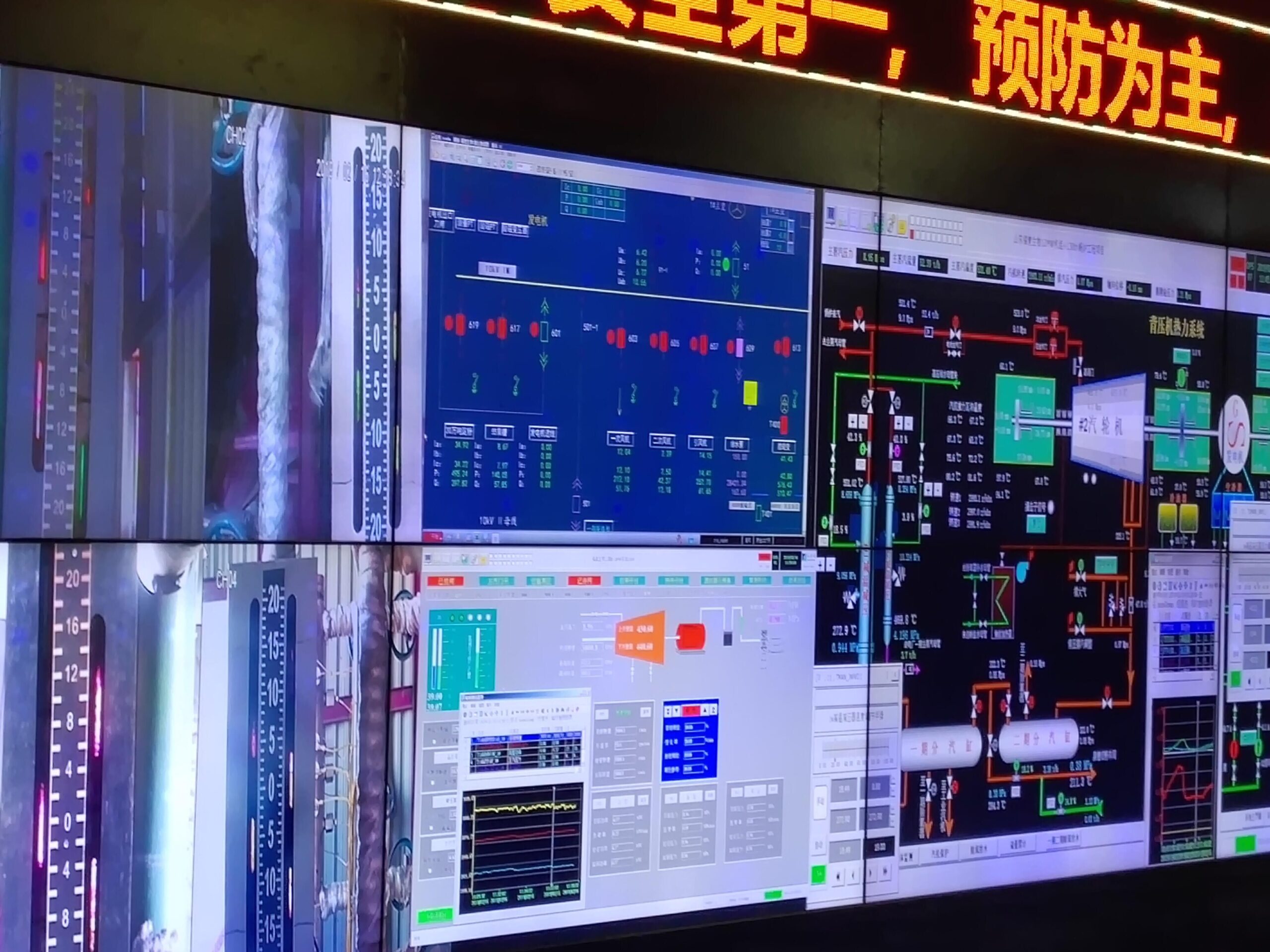
How do modern control systems optimize CFB boiler performance and emissions?
In Circulating Fluidized Bed (CFB) boilers, maintaining optimal combustion, temperature, pressure, and fluidization conditions is crucial for efficiency and emissions control. Traditional control methods often struggle to respond dynamically to variations in fuel quality, load demands, and environmental requirements. This can lead to poor combustion, excessive fuel consumption, and regulatory violations. The adoption of modern control systems—leveraging automation, data analytics, and real-time feedback—has revolutionized the operation of CFB boilers. These systems not only maintain performance within tight margins but also ensure environmental compliance and cost efficiency.
Modern control systems in CFB boilers optimize performance and emissions by continuously monitoring and adjusting key parameters such as bed temperature, air distribution, fuel feed rate, and flue gas composition through advanced sensors and automated feedback loops. These systems integrate distributed control systems (DCS), programmable logic controllers (PLC), and real-time analytics to achieve stable combustion, reduce pollutant formation, and maximize thermal efficiency across varying load conditions.
Equipped with intelligent algorithms, these systems enable dynamic control of complex processes inherent to CFB operations. They also empower operators to identify inefficiencies, preempt faults, and adapt to diverse fuel types more effectively.
Modern control technologies are essential in unlocking the full potential of CFB boiler systems. In the sections below, we explore how they work, what tools they include, and the measurable benefits they provide to plant performance and environmental management.
The Foundation: Control Architecture in CFB Boilers
| Component | Role in Optimization |
|---|---|
| Distributed Control System (DCS) | Central command for all process parameters |
| Programmable Logic Controllers (PLCs) | Localized control of mechanical components |
| Human-Machine Interface (HMI) | Real-time visualization and operator interaction |
| Supervisory Control and Data Acquisition (SCADA) | Historical data analysis and system-wide monitoring |
| Field Sensors and Transmitters | Data collection from temperature, pressure, flow, emissions |
A typical CFB boiler control structure is hierarchical. At the field level, smart sensors provide continuous data to PLCs and DCS units. These feed real-time information into control algorithms, which adjust air flow rates, fuel feeders, and bed inventory controls to maintain optimal combustion conditions.
Key Control Parameters and Their Impact
| Control Parameter | Optimization Purpose | Outcome |
|---|---|---|
| Bed Temperature | Prevent sintering, maintain fluidization | Stable combustion, reduced NOx/SOx formation |
| Primary/Secondary Air Ratio | Control fluidization and combustion efficiency | Optimal fuel-air mix, lower CO and NOx levels |
| Fuel Feed Rate | Match load and combustion demand | Avoid excess fuel waste, maintain steam output |
| Flue Gas Composition | Monitor pollutants like NOx, SOx, CO, and O₂ | Real-time emissions control |
| Furnace Pressure | Maintain draft balance and air flow | Prevent backflow, improve thermal balance |
Real-Time Feedback Loop: The Heart of Modern Control
In a real-world CFB plant, conditions such as fuel moisture content and particle size can vary significantly. Modern control systems use Proportional-Integral-Derivative (PID) loops, fuzzy logic, or even AI-based adaptive controllers to adjust in real-time based on incoming sensor data.
For instance, if flue gas O₂ concentration rises above target (suggesting excess air and heat loss), the control system automatically reduces secondary air supply and adjusts fuel feed to restore optimal conditions. This is done without manual intervention, enhancing responsiveness and minimizing error.
Performance Optimization via Advanced Data Analytics
Many CFB systems now incorporate predictive analytics and machine learning. These tools analyze historical performance data to detect patterns that precede issues like bed agglomeration, emissions spikes, or thermal imbalance. Predictive maintenance can be triggered based on:
Unusual fluctuations in furnace temperature
Decline in fluidization efficiency
Rising differential pressure across the cyclone or return loop
Emissions Management and Regulatory Compliance
Regulatory standards (e.g., EU Industrial Emissions Directive, US EPA MACT standards) set strict limits on NOx, SOx, CO, and particulate emissions. Modern control systems are programmed with compliance targets and use Continuous Emission Monitoring Systems (CEMS) to adjust combustion settings accordingly.
Emissions Reduction Strategies Enabled by Control Systems:
Staged combustion: Reduces NOx by controlling oxygen availability at each combustion stage.
SOx reduction via sorbent dosing: Automated limestone injection adjusts based on SO₂ sensor feedback.
Optimized cyclone operation: Enhances particulate separation, reducing stack emissions.
| Emission Type | Manual Control Result | Modern Control Result |
|---|---|---|
| NOx | 150–200 mg/Nm³ | 70–100 mg/Nm³ |
| SO₂ | 400–600 mg/Nm³ | 150–300 mg/Nm³ |
| CO | 200–300 mg/Nm³ | <100 mg/Nm³ |
| Particulates | ~50 mg/Nm³ | <30 mg/Nm³ |
Case Study: CFB Boiler Upgrade in Southeast Asia
A 100 MW CFB boiler burning high-ash coal and biomass was retrofitted with a modern DCS and AI-powered emissions control module. Key outcomes:
Thermal efficiency improved by 8.7%
Fuel consumption reduced by 6%
NOx and SO₂ emissions dropped by 45% and 50%, respectively
Maintenance downtime cut by 30% due to predictive alerts
Operator Support and System Diagnostics
| Feature | Benefit to Operations |
|---|---|
| Alarm Management | Prioritizes faults by severity and impact |
| Trend Analysis | Identifies drift in process parameters |
| Auto-Tuning Controllers | Adjusts PID gains for dynamic load response |
| Diagnostic Dashboards | Pinpoints faulty valves, sensors, or control loops |
Comparison Chart: Traditional vs Modern CFB Boiler Controls
| Feature | Traditional Controls | Modern Controls (DCS/AI-based) |
|---|---|---|
| Real-time Adjustment | Manual or slow | Instantaneous, automated |
| Sensor Integration | Limited | Wide, multi-parameter |
| Load Following Capability | Limited | Adaptive and efficient |
| Emissions Management | Reactive | Proactive and dynamic |
| Fault Detection | Manual inspection | Predictive analytics |
| Data Logging | Local records | Centralized, cloud-enabled |
Integration Best Practices
Calibrate sensors regularly for accurate feedback
Train operators in HMI use and fault diagnostics
Use cybersecurity protocols to protect DCS/PLC systems
Integrate with plant-wide SCADA for coordinated control
By replacing manual or semi-automatic systems with intelligent, digital control systems, CFB boilers can dramatically boost performance, lower emissions, and provide higher reliability. In an age of strict environmental standards and economic pressure, these systems are no longer a luxury—they are a strategic necessity.
🔍 Conclusion
Circulating Fluidized Bed boilers are highly flexible, fuel-efficient, and environmentally friendly systems. Each component, from the air distributor to the cyclone separator, plays a vital role in maintaining stable fluidization, efficient combustion, and precise heat recovery. By understanding the design and function of these key components, operators can optimize system performance, reduce downtime, and achieve regulatory compliance.
📞 Contact Us
💡 Looking to improve your CFB boiler’s efficiency or considering a new installation? Our expert team provides tailored solutions for design, maintenance, and performance optimization.
🔹 Reach out today to enhance your boiler operation with cutting-edge CFB technology! 🔄🔥
FAQ
What are the main components of a circulating fluidized bed (CFB) boiler?
Key components include the fluidized bed combustion chamber, air distributor, cyclone separator, heat exchanger, solids return system, and emission control units.
What is the function of the fluidized bed in a CFB boiler?
The fluidized bed allows fuel particles to be suspended and mixed with air, enhancing combustion efficiency and heat transfer in the boiler.
How does the cyclone separator work in a CFB boiler?
The cyclone separator captures solid particles from flue gas and returns them to the combustion chamber, improving combustion and reducing emissions.
Why is the solids return system important in CFB boilers?
It recycles unburnt fuel and ash particles back into the combustion chamber, increasing fuel efficiency and minimizing waste.
How do CFB boilers manage emissions?
CFB boilers use in-bed desulfurization with limestone and selective non-catalytic reduction (SNCR) systems to reduce SO₂ and NOx emissions effectively.
References
Circulating Fluidized Bed Combustion Basics – https://www.energy.gov
CFB Boiler Technology Overview – https://www.sciencedirect.com
How Cyclone Separators Work – https://www.researchgate.net
Emission Control in CFB Boilers – https://www.epa.gov
Fluidized Bed Combustion Explained – https://www.bioenergyconsult.com
CFB vs. Pulverized Coal Boilers – https://www.mdpi.com
Advanced Boiler Design for CFB Systems – https://www.energysavingtrust.org.uk
Efficiency of CFB Boilers – https://www.iea.org
CFB Boiler Operation and Maintenance – https://www.automation.com
CFB Combustion System Details – https://www.sciencedirect.com