Industry News

How Fuel Types & Combustion Affect Industrial Gas-Fired Boiler Selection

How Fuel Types & Combustion Affect Industrial Gas-Fired Boiler Selection

When selecting an industrial gas-fired boiler, many buyers focus primarily on size, pressure, and cost—yet fuel type and combustion properties are equally critical. Choosing the wrong configuration for your specific gas type can lead to inefficient combustion, higher emissions, equipment damage, and excessive operational costs. To ensure maximum performance, safety, and long-term value, it’s essential to understand how different gas fuels and their combustion behaviors influence boiler selection and design.

Fuel types and combustion characteristics affect your choice of industrial gas-fired boiler by influencing burner design, flame stability, combustion temperature, emissions profile, and heat transfer efficiency. Common fuel gases like natural gas, liquefied petroleum gas (LPG), biogas, and hydrogen blends differ in calorific value, pressure, ignition properties, and combustion air requirements. These differences impact boiler configuration, safety systems, emission controls, and automation settings. A properly matched boiler-fuel setup is essential for optimized performance, minimal downtime, and regulatory compliance.

Whether you’re using pipeline natural gas or considering alternative fuels like biogas or hydrogen, the right knowledge ensures a safer and more cost-effective investment.

What Types of Fuel Gases Are Commonly Used in Industrial Gas-Fired Boilers?

In industrial production and heating systems, gas-fired boilers are the heartbeat of operations—but choosing the wrong fuel gas can lead to higher costs, increased emissions, and efficiency issues. Many users face the dilemma of understanding which type of fuel gas is most suitable for their specific application. A misstep here not only impacts performance but could also result in non-compliance with environmental standards. The solution lies in knowing the characteristics, advantages, and limitations of each commonly used industrial fuel gas. This article provides a comprehensive guide to help you make informed decisions when selecting a fuel gas for your industrial gas-fired boiler.

The most commonly used fuel gases in industrial gas-fired boilers include natural gas, liquefied petroleum gas (LPG), biogas, and syngas. Natural gas is the dominant choice due to its high calorific value, clean combustion, and wide availability. LPG, primarily composed of propane and butane, is favored for its portability and higher heating value per volume. Biogas and syngas are often used in waste-to-energy and biomass applications due to their renewable nature, although they require specific burner designs.

Understanding the pros and cons of each type of fuel gas is essential for industrial facility managers, procurement officers, and engineers. The remainder of this article explores their properties, performance, efficiency, environmental impacts, and typical applications in gas-fired boilers.

Natural gas is the most commonly used fuel in industrial gas-fired boilers.True

Natural gas is widely used because of its high energy content, clean combustion, and established distribution networks.

Key Characteristics of Common Industrial Boiler Fuel Gases

Industrial gas-fired boilers are engineered to work with specific fuel gas types based on combustion characteristics, availability, and cost. Below is a comprehensive overview of each major fuel gas category:

Natural Gas

Natural gas, composed mainly of methane (CH₄), is the most popular choice for industrial boilers due to its clean-burning properties and efficient heat generation. It has a high calorific value, typically around 38 MJ/m³, and a relatively low carbon footprint compared to other fossil fuels.

PropertyNatural Gas
Main ComponentMethane (CH₄)
Heating Value35–40 MJ/m³
Flame Temperature~1,950°C
AvailabilityHigh (via pipelines)
Environmental ImpactLow CO₂, very low SOx/NOx

Technical Considerations:

  • Requires precise air-fuel ratio control

  • Low impurity levels reduce maintenance

  • Standard in most developed industrial networks

Liquefied Petroleum Gas (LPG)

LPG is a blend of propane (C₃H₈) and butane (C₄H₁₀), offering higher energy density than natural gas, making it ideal for remote sites lacking pipeline access.

PropertyLPG (Propane/Butane)
Heating Value~93 MJ/m³ (propane)
StoragePressurized tanks
Flame Temperature~1,980°C
TransportabilityHigh
Environmental ImpactCleaner than diesel/oil

Technical Considerations:

  • Requires pressurized tanks and regulators

  • Burner compatibility must be ensured

  • Higher carbon content than natural gas

Biogas

Biogas is produced via anaerobic digestion of organic waste, primarily containing methane and carbon dioxide. It is a renewable energy source and often used in conjunction with wastewater treatment or agricultural operations.

PropertyBiogas
Methane Content50–70%
Heating Value20–25 MJ/m³
CO₂ Content30–50%
SourceOrganic waste
Environmental ImpactRenewable, carbon-neutral

Technical Considerations:

  • Requires gas scrubbing/purification

  • Variable composition affects burner tuning

  • Needs corrosion-resistant components

Syngas (Synthetic Gas)

Syngas is produced via gasification of coal, biomass, or waste. It contains hydrogen, carbon monoxide, and traces of methane, making it highly versatile but challenging to manage.

PropertySyngas
CompositionH₂, CO, CH₄, CO₂
Heating Value10–20 MJ/m³
SourceBiomass, waste, coal
StorageOn-demand production
Environmental ImpactLow to moderate (depends on source)

Technical Considerations:

  • Requires custom burner systems

  • Lower calorific value needs compensation in design

  • High combustion control precision is necessary

Comparison Table of Fuel Gas Suitability for Industrial Boiler Applications

Fuel Gas TypeEnergy DensityClean CombustionCost EffectivenessAvailabilityBoiler Compatibility
Natural GasHighExcellentHighExcellentBroad
LPGVery HighVery GoodModerateGoodRequires adjustment
BiogasMediumGood (if purified)Low (if in-house)Site-dependentCustom design required
SyngasLow to MediumVariableModerateModerateSpecialized equipment

Advanced Considerations in Fuel Gas Selection

H3: Environmental Compliance

Industrial boilers must comply with regional emission limits for NOx, SOx, CO₂, and particulates. Natural gas and biogas offer the lowest emissions, while LPG emits slightly more CO₂ per unit of energy due to its higher carbon content.

H3: Burner and Control System Adaptability

Each fuel gas demands a distinct burner design and control strategy:

  • Natural gas burners feature premix or nozzle-mix designs.

  • LPG systems require adjustable orifices and flame retention heads.

  • Biogas and syngas require real-time combustion monitoring and oxygen trimming systems due to inconsistent calorific values.

Gas TypeRequires Gas Train Modifications?Air-Fuel Ratio ToleranceControl System Complexity
Natural GasNoNarrowStandard
LPGYes (pressure reduction)ModerateModerate
BiogasYes (scrubber, filters)WideHigh
SyngasYes (burner redesign)Very WideVery High

H3: Real-World Case Study – Switching from Diesel to Natural Gas

A textile manufacturer in Bangladesh transitioned its 10-ton steam boiler from diesel to natural gas. The switch resulted in:

  • 30% fuel cost savings

  • 60% lower carbon emissions

  • Improved combustion efficiency (from 78% to 92%)

However, the change required:

  • New burner retrofitting

  • Pipeline connection to local gas grid

  • Automated safety controls upgrade

Ending Summary

Selecting the right fuel gas for industrial gas-fired boilers is not just about energy cost—it’s about optimizing system efficiency, ensuring environmental compliance, and matching technical compatibility. From natural gas and LPG to renewable biogas and engineered syngas, each option offers unique advantages and requires careful evaluation. For many operations, natural gas remains the best combination of performance, availability, and emission control. Meanwhile, biogas and syngas are gaining ground in green industrial applications. A detailed analysis of fuel properties, combustion dynamics, and local infrastructure is essential for long-term success.

How Do Calorific Value and Combustion Air Ratio Affect Boiler Sizing and Efficiency?

In industrial heating and process environments, selecting the right boiler size and maximizing combustion efficiency is vital for energy savings and environmental compliance. However, many users overlook the critical impact of two fundamental combustion parameters: the calorific value of the fuel and the combustion air ratio. Misjudging these can lead to undersized or oversized boilers, wasted fuel, increased emissions, and even premature equipment failure. Understanding the interplay between fuel energy content and air-to-fuel mixture is key to optimizing boiler design and operation. This article will guide you through how calorific value and combustion air ratio directly influence boiler sizing and efficiency.

Calorific value determines the amount of energy a fuel can release during combustion, while the combustion air ratio governs how efficiently that energy is converted into usable heat. A higher calorific value allows smaller boilers to produce the same energy output, while an improper air ratio—especially excess air—reduces efficiency by absorbing heat into unused oxygen and nitrogen. Together, these two parameters critically affect boiler sizing, thermal performance, and fuel economy.

If you’re designing or upgrading a boiler system, getting these two parameters right is essential to avoid energy waste and oversized equipment. Let’s now dive deeper into the technical mechanics and practical implications of each.

Higher calorific value fuels require smaller boilers to achieve the same thermal output.True

Boilers are sized based on the heat input required to meet thermal demands, so a fuel with higher energy content reduces the volume of combustion gases and the heat exchanger surface area needed.

Understanding Calorific Value in Boiler Sizing

The calorific value (CV) of a fuel is the amount of energy released during complete combustion of a unit quantity of the fuel—usually expressed in MJ/m³ for gases or MJ/kg for solids/liquids. It directly determines how much fuel is needed to achieve a desired thermal output.

Fuel TypeGross CV (MJ/m³)Net CV (MJ/m³)Typical Use in Boilers
Natural Gas38–4235–39Standard industrial boiler fuel
LPG (Propane)~93~85Off-grid or mobile applications
Biogas20–2517–22Renewable energy & digestion sites
Syngas10–208–17Biomass, waste-to-energy
Diesel (liquid)45–46 MJ/kg~43 MJ/kgBackup and mobile boilers

Calorific Value and Boiler Sizing Formula

The required boiler thermal input is calculated using the desired output and system efficiency.

Then, the fuel flow rate needed depends on the CV:

Higher CV → Lower fuel flow rate → Smaller combustion chamber → Smaller boiler footprint.

Example: To generate 1,000 kW of steam at 90% efficiency:

  • Using natural gas (CV = 38 MJ/m³):

    10000.9=1111 kW input⇒111138=29.2 m³/h gas\frac{1000}{0.9} = 1111 \text{ kW input} \Rightarrow \frac{1111}{38} = 29.2 \text{ m³/h gas}

  • Using biogas (CV = 22 MJ/m³):

    111122=50.5 m³/h gas\frac{1111}{22} = 50.5 \text{ m³/h gas}

This affects burner size, combustion chamber design, and heat exchanger dimensions.

Combustion air ratio has little effect on boiler efficiency.False

Excess air beyond optimal levels reduces boiler efficiency by carrying away heat in flue gases and lowering flame temperature.

Combustion Air Ratio and Its Efficiency Impact

The combustion air ratio is the ratio of actual air supplied to the stoichiometric air required for perfect combustion. This ratio profoundly impacts flame stability, combustion completeness, and heat loss in flue gases.

Air Ratio (λ)DescriptionTypical Efficiency Impact
λ = 1.0Stoichiometric (ideal)Theoretical max, but unsafe
λ = 1.1–1.3Controlled excess airPeak practical efficiency
λ > 1.5High excess airEfficiency drop >5–10%
λ < 1.0Air-deficient (rich flame)CO formation, safety hazard

How Excess Air Affects Efficiency

When excess air increases:

  • More cold air enters combustion chamber → Heat absorbed by nitrogen and unused oxygen

  • Flue gas temperature rises without increasing useful heat → Lost energy

  • Flame temperature drops → Incomplete combustion, higher CO emissions

Air RatioTypical Stack Temp (°C)Boiler Efficiency (%)
1.118091
1.322089
1.527085
2.032080

Maintaining optimal air ratio is critical to reducing fuel usage and meeting emissions standards.

Interaction Between Calorific Value and Air Ratio

When evaluating both parameters for sizing and performance:

  • Low-CV fuels (e.g., biogas, syngas) require larger combustion chambers and higher air flow → increased flue gas volume and pressure loss

  • High-CV fuels enable compact burner design but demand precise air ratio control due to hotter flame temperatures

  • For fuels with variable CV (biogas, landfill gas), adaptive combustion controls and oxygen trim systems are essential

FuelCVIdeal λKey Control Strategy
Natural GasHigh1.1–1.2PID + O₂ trim
LPGVery High1.1Tight excess air margin
BiogasLow1.3–1.5Real-time calorific adjustment
SyngasLow1.4–1.7Variable burner + flame monitoring

Practical Boiler Design Implications

Combustion Chamber Sizing

Boiler designers must ensure the combustion chamber volume matches the flame length and heat release rate, both of which are affected by:

  • Fuel CV: Lower CV → larger volume needed

  • Air ratio: Excess air → longer flame, higher flue volume

Burner Design and Control System

Efficient combustion systems rely on:

  • Modulating burners matched to fuel CV

  • Accurate air-fuel ratio control using:

    • Mass flow meters

    • O₂ sensors

    • Variable frequency drives (VFDs) for fans

Case Example: Biogas Conversion Challenges

A wastewater treatment plant retrofitted a 4-ton/hr boiler to run on biogas. Due to biogas’s low and variable CV:

  • Burner was redesigned with wider flame stability range

  • Air-fuel controller installed with CV feedback loop

  • Combustion chamber lengthened to ensure complete burn

The result:

  • 15% efficiency drop compared to natural gas baseline

  • However, net operating cost was 40% lower due to on-site fuel use

Final Thoughts

Both calorific value and combustion air ratio play decisive roles in boiler sizing and thermal efficiency. Calorific value determines how much heat can be extracted per unit of fuel and affects everything from burner sizing to heat exchanger area. Meanwhile, the combustion air ratio governs how efficiently this energy is used, with excessive air leading to significant heat losses. Mastering these parameters is essential not only for technical optimization but also for sustainable energy use and compliance with environmental standards.

Why Is Burner Compatibility Critical for Different Gas Fuels?

When industries switch between gas fuels or design systems for multi-fuel flexibility, burner compatibility is often underestimated—leading to serious safety risks, poor combustion, low thermal efficiency, and even equipment failure. Each gas fuel has unique physical and chemical characteristics that influence how it burns, such as flame speed, calorific value, and air requirements. Using a burner not designed for the specific gas type can result in unstable flames, carbon monoxide formation, or overloading of combustion components. The solution lies in choosing or modifying burners to precisely match the fuel characteristics. This article unpacks why burner compatibility is so critical when dealing with different gas fuels.

Burner compatibility is critical because each gas fuel has distinct combustion properties—including flame speed, calorific value, ignition temperature, and air-to-fuel ratio—that must match the burner’s design. Mismatched burners can lead to unstable combustion, incomplete fuel burn, dangerous emissions like CO, and system inefficiencies. Therefore, burner selection or modification must align precisely with the physical and chemical profile of the intended fuel gas.

Understanding burner compatibility allows engineers and facility operators to safely switch fuels, optimize combustion, and reduce operational costs. Let’s explore the technical reasons and practical consequences of matching burners to specific gas fuels.

A burner designed for natural gas can be used safely with LPG without modification.False

LPG has a significantly higher calorific value and different combustion properties than natural gas, requiring nozzle and pressure adjustments or burner redesign for safe and efficient operation.

How Gas Fuel Properties Affect Burner Design

Each type of gas fuel interacts uniquely with combustion components. Key parameters that influence burner compatibility include:

PropertyNatural GasLPGBiogasSyngas
Calorific Value (MJ/m³)38–4293–10020–2510–20
Flame Speed (m/s)ModerateFastSlowVariable (low–med)
Stoichiometric Air Ratio~10:1~24:1~6:1~1–2:1
Ignition Temp (°C)~600~470~650500–700
Moisture/CO₂ ContentLowLowHighMedium

These differences demand specific burner characteristics:

  • Orifice size

  • Air mixing method (premix vs. nozzle mix)

  • Turbulence control

  • Flame stabilization technique

  • Control system tuning

If not adjusted, the burner may fail to ignite, experience flame lift-off, or produce excess emissions.

Burner-Fuel Compatibility Matrix

Fuel GasStandard NG BurnerModified NG BurnerDedicated Burner RequiredWhy?
Natural GasDesigned match
LPGOptionalRequires orifice & pressure mods
BiogasHigh CO₂, low CV needs custom burner
SyngasHighly variable composition
HydrogenUltra-fast flame speed

Important Note: Even if fuels seem similar, such as natural gas and LPG, they differ significantly in CV and density, requiring dedicated adjustments in burner pressure settings and mixing orifice geometry.

Key Burner Design Parameters Influenced by Fuel

Flame Stabilization

Burners must create a stable flame envelope to prevent flame lift-off or flashback. Fuels like LPG and hydrogen with high flame speeds require flame arrestors and high-velocity ports to control flame travel.

Mixing and Combustion Air Control

Different fuels need different air-fuel premix strategies:

  • Biogas and syngas require low excess air and recirculation support to maintain flame temperature.

  • LPG and natural gas demand precise venturi or nozzle mixing to avoid incomplete combustion.

FuelAir-Fuel Mixing StrategyAir Control Complexity
Natural GasVenturi premix or nozzle mixMedium
LPGVenturi with adjusted jetsHigh (due to volatility)
BiogasNozzle mix, staged airVery High
SyngasNozzle mix with dynamic controlExtreme (real-time adaptation)

Burner Material and Construction

Some gas fuels (e.g., biogas, syngas) contain corrosive compounds like H₂S, CO₂, or NH₃, which corrode metal parts:

  • Stainless steel burners may be required

  • Ceramic coatings or gas pre-treatment is advised

Consequences of Incompatible Burner Use

ProblemResulting Impact
Flame instabilityBlow-off, flashback, burner damage
Incomplete combustionHigh CO, soot, low thermal efficiency
Overheating of burner surfaceBurner deformation, premature failure
Incorrect air-fuel ratioLow flame temp, excessive flue loss
Poor ignition reliabilityShutdowns, safety risks

Case Study Example: LPG in Natural Gas Burner

A facility in Turkey attempted to run LPG on an unmodified NG burner. The result:

  • Burner tip overheated due to higher flame temp

  • Flame lifted from the burner mouth

  • Excess CO detected in exhaust

  • System required emergency retrofit with smaller jets and regulator change

The cost of repair exceeded $25,000 including downtime.

Key Burner Design Types and Fuel Suitability

Burner TypeBest Fuel MatchesNotes
Premix BurnerNG, LPG (with mods)Excellent flame control, sensitive to pressure
Nozzle Mix BurnerBiogas, syngas, mixed gasGood for variable CV and staged combustion
Dual-Fuel BurnerNG/LPG or NG/OilRequires auto-switching systems
Flare/Low CV BurnersBiogas, landfill, syngasHigh tolerance for impurities, low flame speed
Hydrogen BurnerHydrogen, NG blendsMust prevent flashback and need special materials

Modern Solutions for Multi-Fuel Compatibility

To safely operate with different gas fuels, burners must feature:

  • Adaptive air-fuel ratio control

  • Flame ionization sensors

  • Oxygen trim systems

  • Modular orifice kits

  • Dual manifold systems

Manufacturers now offer smart burners with:

  • Integrated calorific value sensors

  • Real-time fuel composition adjustment

  • Cloud-based burner performance monitoring

These ensure safe switching and consistent performance across multiple fuels.

Summary

Burner compatibility is essential for reliable, efficient, and safe combustion in gas-fired boilers. Because each fuel type exhibits distinct energy content, density, ignition behavior, and air requirements, burner designs must be carefully matched or modified to accommodate these properties. Failing to do so not only compromises performance but also introduces serious safety and maintenance issues. Whether you’re switching fuels or designing for multi-fuel flexibility, understanding burner-gas interaction is non-negotiable for long-term operational success.

How Do Fuel Impurities and Moisture Content Impact Combustion Performance?

In industrial combustion systems, even a seemingly small level of fuel impurity or moisture can wreak havoc on performance, emissions, and equipment lifespan. Fuel impurities such as sulfur, chlorine, and siloxanes, along with high moisture content, often lead to incomplete combustion, corrosion, scaling, and increased fuel consumption. Many operators fail to consider these factors during fuel procurement or boiler design, leading to unplanned maintenance, emissions violations, and lower thermal efficiency. To avoid these pitfalls, it is essential to understand how fuel quality, particularly impurity levels and moisture content, directly influences combustion dynamics and system reliability.

Fuel impurities and moisture content significantly reduce combustion performance by lowering flame temperature, increasing unburned hydrocarbons and CO emissions, and accelerating corrosion and fouling in heat exchangers. Moisture absorbs latent heat during vaporization, reducing overall energy output, while impurities like sulfur and chlorine form corrosive compounds that damage boiler internals. Clean, dry fuel is crucial for efficient and stable combustion.

These issues are especially relevant in boilers using non-traditional or renewable fuels like biogas, syngas, or waste-derived gases. Let’s dive deep into the physics and chemistry behind how fuel quality affects combustion performance.

High moisture content in fuel improves combustion efficiency by reducing flame temperature.False

Moisture in fuel absorbs significant heat during vaporization, lowering flame temperature and reducing combustion efficiency.

Chemical and Physical Impacts of Fuel Moisture

H3: How Moisture Affects Combustion Energy Balance

Moisture in fuel does not contribute to combustion but instead absorbs heat during vaporization (enthalpy of vaporization ~2,260 kJ/kg for water). This process pulls energy from the flame zone, reducing overall thermal efficiency.

ParameterDry FuelFuel with 20% Moisture
Calorific Value (CV)38 MJ/m³~30 MJ/m³
Flame Temperature (°C)1,950~1,780
Combustion Efficiency (%)90–9275–85

This means the boiler must burn more fuel to achieve the same heat output, increasing operational costs.

H3: Real Case – Moist Biogas Effect

A paper mill using biogas with ~10% water vapor noted:

  • 12% drop in flame temperature

  • 8% increase in fuel flow rate

  • Fluctuating flame stability

Solution: A gas dehydration skid using condensation and membrane separation improved flame stability and reduced gas usage by 10%.

Impact of Fuel Impurities on Combustion and Equipment

Fuel impurities vary depending on fuel type. Here’s a summary of common impurities and their combustion impacts:

ImpurityCommon SourceCombustion ImpactResulting Problem
H₂SBiogas, landfill gasConverts to SO₂, reacts with water to form sulfuric acidCorrosion, acid dewpoint issues
SiloxanesWaste gas, landfillForm silicon dioxide on hot surfacesAbrasive deposits on burners/turbines
ChlorineWaste gas, PVC-derivedConverts to HCl, corrosive to stainless steelRapid corrosion, toxic emissions
Dust/ParticulatesBiomass syngasDo not burn, collect on boiler surfacesFouling, poor heat transfer
TarLow-temp gasificationIncomplete combustion, clogs nozzlesBurner fouling, instability

Siloxane impurities in biogas can damage burner nozzles and heat exchangers.True

Siloxanes form hard silicon dioxide deposits when combusted, causing abrasive damage to metal surfaces and impairing heat transfer.

Impact on Burner and Combustion Control

Burners must maintain a stable flame and correct stoichiometric ratio, but impurities can:

  • Alter flame ionization → Misleading flame detection

  • Increase NOx and CO → Fail emissions compliance

  • Cause deposit buildup → Distorted flame patterns and backpressure

Burner EffectCauseMitigation Strategy
Flame Lift/Blow-offLow CV from moisturePre-drying, preheating fuel
Burner Tip CloggingTar, particulatesCyclone separators, filters
Flame InstabilityVariable CV, siloxanesReal-time CV monitoring, adaptive controls
High CO FormationH₂S, insufficient air mixSecondary air injection, precise control loops

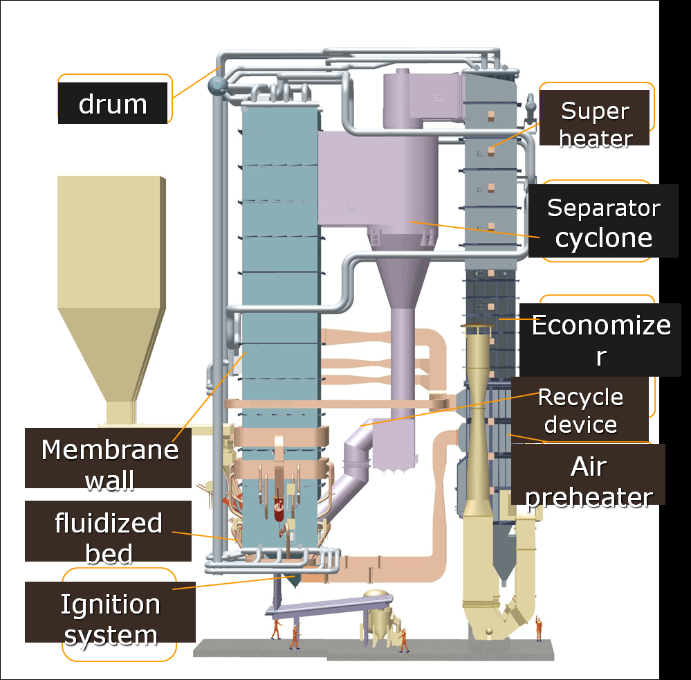
Heat Exchanger and Boiler Tube Impacts

Impurities also damage downstream equipment:

ComponentImpurity EffectFailure Mode
Superheater TubesHCl, SO₂, alkali saltsPitting, thinning, creep
EconomizersDust, sulfur compoundsPlugging, acid corrosion
Air PreheatersCondensable moisture and chloridesCorrosion under deposit
CondensersHCl and H₂SO₄ condensationAcid dew point corrosion

Example: In a syngas-fired CHP plant, failure of superheater tubes was traced to vanadium-sodium chloride deposits forming a low-melting eutectic, causing localized overheating.

Moisture & Impurity Tolerance by Fuel Type

Fuel TypeMoisture ToleranceImpurity SensitivityRequired Pre-treatment
Natural GasVery LowVery LowMinimal (dry pipeline-grade)
LPGLowLowNone
BiogasHighHigh (H₂S, siloxanes)Scrubbing, drying, filtration
SyngasMediumVery High (tars, Cl)Cooling, tar cracking, acid gas removal
Landfill GasHighVery High (siloxanes, H₂S)Activated carbon, dehydration

Key Equipment for Fuel Treatment

To mitigate the effects of impurities and moisture, modern boiler systems integrate:

  • Gas scrubbers: Remove H₂S, NH₃

  • Chillers and condensers: Reduce moisture

  • Siloxane adsorbers: Protect turbines and burners

  • Particulate filters: Prevent clogging and fouling

  • Tar reformers: Gasify heavy hydrocarbons in syngas

These systems not only improve combustion performance but also extend equipment life and reduce downtime.

Summary

Moisture and fuel impurities significantly degrade combustion performance, reduce efficiency, and increase maintenance costs in industrial gas-fired boilers. Moisture absorbs energy without contributing to combustion, while impurities form corrosive, toxic, or abrasive by-products that damage equipment and increase emissions. Advanced fuel treatment systems and burner adaptation are essential for stable, clean, and cost-effective operation—especially when using biogas, syngas, or other low-grade fuels. Understanding and managing these contaminants ensures long-term reliability and high combustion efficiency.

What Emissions Control Systems Are Needed for Various Gas Types?

Industrial gas-fired boilers must comply with strict air emission regulations that vary by region and fuel type. Yet many facilities underestimate the importance of customizing emissions control systems based on the specific gas used. Emissions such as nitrogen oxides (NOx), carbon monoxide (CO), sulfur oxides (SOx), particulate matter (PM), and volatile organic compounds (VOCs) are highly dependent on fuel composition, combustion temperature, and burner design. Without appropriate control systems, emissions can easily exceed legal limits, exposing businesses to fines, shutdowns, and environmental harm. Understanding which emission control technologies to use for each fuel gas type is essential for regulatory compliance and sustainable operation.

Different gas fuels produce distinct emissions profiles requiring specific control systems. Natural gas requires low-NOx burners and selective catalytic reduction (SCR) for NOx; LPG needs similar NOx controls but typically doesn’t require sulfur or particulate controls. Biogas and syngas, on the other hand, often require desulfurization systems, particulate filters, and activated carbon for VOCs and siloxanes. Matching control technologies to the combustion byproducts of each gas is critical for clean, compliant, and efficient operation.

Let’s examine in detail how emissions vary with fuel type and the required emissions control strategies for each, backed by technical insights and system design data.

Natural gas combustion typically requires desulfurization equipment to reduce SO₂ emissions.False

Natural gas contains negligible sulfur, so SO₂ emissions are minimal, and desulfurization is generally not needed.

Fuel-Specific Emissions Profile and Required Controls

Each fuel type has unique chemical properties that influence its emission output. The table below summarizes typical pollutants and the required control technologies for each gas:

Gas TypeMain PollutantsControl Systems Required
Natural GasNOx, COLow-NOx burner, Flue gas recirculation (FGR), SCR
LPGNOx, COLow-NOx burner, combustion tuning
BiogasNOx, CO, H₂S, siloxanesSCR/SNCR, Desulfurization, Activated carbon, Filters
SyngasNOx, CO, tars, PM, HClWet scrubbers, Baghouse filters, SCR, Acid gas removal
Landfill GasH₂S, siloxanes, VOCsActivated carbon, Biological scrubbers, Pre-filtering
HydrogenNOx (from high flame temp)Ultralow-NOx burners, FGR, staged combustion

Emissions Control Systems – Technical Overview

H3: NOx Control Systems

NOx (nitrogen oxides) are produced due to high flame temperatures. Control technologies include:

TechnologyDescriptionBest For
Low-NOx BurnersBurners that limit flame temperature or stage air/fuelNG, LPG, Biogas
Flue Gas Recirculation (FGR)Recirculates cooled flue gas to reduce flame tempNG, hydrogen
Selective Catalytic Reduction (SCR)Uses ammonia/urea and catalyst to convert NOx to N₂ and H₂OAll high-NOx fuels
Selective Non-Catalytic Reduction (SNCR)Direct urea/ammonia injection at 850–1100°CSmaller-scale biogas, syngas

Case Study: A brewery using biogas saw a 40% NOx reduction after installing an SCR system combined with low-NOx burners, maintaining emissions at 15 ppm.

H3: SOx and H₂S Control Systems

SOx emissions originate from sulfur compounds like H₂S, common in biogas and landfill gas.

TechnologyFunctionFuel Application
Gas Scrubbers (chemical)Absorb H₂S in caustic soda or iron spongeBiogas, landfill gas
Biological DesulfurizationUses bacteria to oxidize H₂SBiogas, cost-effective
Claus ProcessIndustrial-scale sulfur recoveryLarge-scale syngas plants

Biogas with high H₂S content requires desulfurization before combustion.True

Combusting biogas with high H₂S without treatment produces corrosive SO₂ and damages heat exchangers and flues.

H3: CO and VOC Control Systems

Incomplete combustion produces CO and VOCs, which require proper air-fuel ratio management and sometimes post-combustion treatments.

Control MethodDescriptionBest For
Combustion TuningPrecise control of air-to-fuel ratioAll fuels
Catalytic OxidizersOxidize CO and VOCs at lower temps using catalystBiogas, landfill
Thermal OxidizersBurn VOCs at high temps with excess airHigh-VOC syngas streams

H3: Particulate and Tar Control Systems

Tar and PM originate mainly from low-grade syngas and biomass gas.

SystemFunctionFuel Application
Cyclone SeparatorsRemove large particlesSyngas, biomass
Baghouse FiltersTrap fine particulates using filter mediaHigh-dust syngas
Wet ScrubbersCapture PM and dissolve soluble gasesSyngas, acid gases
Electrostatic PrecipitatorsElectrically charge and collect PMLarge-scale syngas

Example: A gasification plant installed both a cyclone and a baghouse filter to reduce PM to <10 mg/Nm³, achieving EU air quality compliance.

H3: Siloxane Control Systems

Siloxanes are unique to landfill and sewage gas. When burned, they form abrasive SiO₂ deposits on turbines and heat exchangers.

Control SystemFunctionFuel Source
Activated CarbonAdsorbs siloxanes and VOCsBiogas, landfill gas
Chilled Condensation UnitsCool gas to condense and remove moisture/siloxanesBiogas
Silica Gel BedsTargeted siloxane captureHigh-siloxane environments

Comparison Chart: Emissions vs Control Needs by Gas Type

Gas TypeNOx ControlSOx/H₂S ControlCO/VOC ControlPM/Tar ControlSiloxane Control
Natural GasLow-NOx burner, SCRNot neededAir-fuel tuningNot neededNot needed
LPGLow-NOx burnerNot neededTuningNot neededNot needed
BiogasSCR, SNCRChemical scrubberCatalytic oxidizerMinimalActivated carbon
SyngasSCR, FGRWet scrubberThermal oxidizerBaghouse/wet scrubberNot needed
Landfill GasSNCRBiological scrubberCatalytic oxidizerMinimalCarbon + chillers
HydrogenFGR, staged burnerNot neededTuningNot neededNot needed

Control Integration and System Design Considerations

Industrial boiler designers must incorporate emissions controls into both upstream fuel processing and downstream flue gas treatment, considering:

  • Fuel variability (e.g., biogas CV or impurity changes)

  • System scalability

  • Cost vs. compliance trade-off

  • Integration with burner and control systems

  • Real-time monitoring (O₂ sensors, stack analyzers)

Modern control systems include:

  • PLC/SCADA for emissions tracking

  • Auto-tuning burners

  • Continuous Emissions Monitoring Systems (CEMS) for reporting compliance

Summary

Selecting appropriate emissions control systems for various gas fuels is essential for environmental compliance, equipment protection, and sustainable operations. While natural gas needs only minimal controls for NOx and CO, fuels like biogas, syngas, and landfill gas demand comprehensive solutions including desulfurization, particulate removal, VOC oxidation, and siloxane capture. A one-size-fits-all approach doesn’t work. Instead, emissions control must be customized to the unique combustion profile of each gas type, integrated into the combustion system, and continually monitored for optimal performance.

How Can Hydrogen or Biogas Integration Impact Future Boiler Design and Retrofits?

As industries shift toward carbon neutrality and energy decentralization, integrating hydrogen and biogas into boiler systems is becoming a necessity rather than a choice. However, these renewable fuels present unique combustion characteristics and engineering challenges that make conventional boiler systems unsuitable without redesign or retrofit. Failure to adapt boilers to the specific demands of hydrogen’s high flame speed or biogas’s moisture and impurity levels can lead to inefficiencies, safety risks, and non-compliance with emissions regulations. The solution lies in proactively reengineering both new and existing boilers to accommodate these low-carbon fuels—creating a future-ready, adaptable heating infrastructure.

Integrating hydrogen or biogas into boiler systems impacts design and retrofit requirements by necessitating burner modifications, combustion control upgrades, fuel conditioning systems, and material changes to withstand new thermal and chemical environments. Hydrogen’s fast flame speed demands flashback prevention and precise air-fuel control, while biogas integration requires impurity removal and moisture management. Designing or retrofitting for these fuels enhances sustainability but involves significant reengineering of core combustion and safety systems.

Industrial users, OEMs, and energy strategists must understand these engineering implications to transition boilers toward clean fuels without compromising safety, performance, or operational reliability. Read on for in-depth design principles, retrofit strategies, and real-world deployment examples.

Hydrogen and biogas can be used in conventional natural gas boilers without any modification.False

Both hydrogen and biogas have combustion properties that differ significantly from natural gas, requiring specific burner designs, control systems, and sometimes material upgrades for safe and efficient use.

Engineering Challenges in Hydrogen and Biogas Combustion

H3: Hydrogen’s Combustion Behavior and Design Needs

Hydrogen is a high-energy, carbon-free fuel with unique combustion traits:

PropertyHydrogenImpact on Boiler Design
Flame Speed~2.9 m/s (very fast)Requires anti-flashback burner design
Ignition Energy0.02 mJ (very low)Needs robust flame detection and isolation
Flame Temperature~2,000–2,100°CHigh-temperature-resistant materials needed
Density~0.089 kg/m³ (low)Higher flow rates and new valve sizing
NOx Formation TendencyVery highDemands staged combustion or FGR

Design Response:

  • Use special flame arrestor mesh in burners

  • Implement multi-stage combustion

  • Apply flue gas recirculation (FGR) for NOx control

  • Upgrade safety systems: double block valves, hydrogen leak detection

H3: Biogas Combustion Characteristics and Design Needs

Biogas is a variable, low-CV fuel with high moisture and impurities:

PropertyBiogasDesign Impact
Calorific Value (CV)~20–25 MJ/m³Larger burner size, longer combustion chamber
CO₂ Content30–50%Reduces flame stability, needs air-fuel tuning
MoistureHighCorrosion risk, affects flame temperature
H₂S and SiloxanesOften presentRequires pre-treatment and material resistance

Design Response:

  • Install gas scrubbers and chillers

  • Use oxidation-resistant alloys for wetted parts

  • Integrate advanced air-fuel ratio control

  • Opt for dual-fuel or biogas-specialized burners

Boiler Retrofit Strategies for Hydrogen & Biogas

Key Components That Must Be Retrofitted or Replaced

Boiler ComponentHydrogen RetrofitBiogas Retrofit
BurnerAnti-flashback, staged designLarge flame stabilizer, impurity-resistant
Fuel Valves & ManifoldHydrogen-rated, leak-proofCorrosion-resistant, moisture handling
Control SystemReal-time lambda and flame sensorsCV sensor and adaptive combustion tuning
Flame DetectionIonization probe, UV/IR sensorMoisture-tolerant, responsive detection
PipingSeamless steel or stainless (hydrogen-ready)Rust-resistant or plastic-lined steel
Heat ExchangerHigh-temp alloys for hydrogen’s hotter flameAnti-scaling design for siloxane removal

Retrofit Timeframe:

  • Light retrofits (e.g., biogas pre-cleaned): ~2–3 weeks

  • Full dual-fuel conversion: ~6–8 weeks

  • Hydrogen-ready conversion: ~3–4 months due to safety testing and compliance

Cost Comparison: Retrofit vs. New Design

Integration StrategyEstimated Cost (USD)Best Fit For
Biogas retrofit (light)$20,000–$60,000Farms, WWTPs, food industries
Hydrogen-ready boiler retrofit$100,000–$250,000District heat, refineries, chemicals
New dual-fuel boiler system$200,000–$500,000+Long-term industrial or institutional

Advanced Control Systems for Mixed Fuel Combustion

Hydrogen and biogas demand adaptive combustion controls for safety and efficiency:

System FeatureFunction
Fuel CV SensorDetects biogas quality in real time
Oxygen Trim ControllerOptimizes excess air
Mass Flow MetersMaintain correct fuel-air ratio
Modulating Burner ControlAdjusts flame shape and intensity
Safety PLC + Flame RelayReacts quickly to flashback or flame loss

Hydrogen-specific addition: Double containment sensors, high-speed shutdown solenoids, and leak-proof interlocks.

Real-World Use Cases: Biogas and Hydrogen Boiler Integration

Case Study 1: Biogas Retrofit in a Brewery

  • Location: Germany

  • System: 6-ton/hr steam boiler

  • Action: Retrofit to use anaerobic digester biogas

  • Upgrades: Activated carbon filter, burner change, CV sensor

  • Result:

    • 40% reduction in natural gas use

    • Payback in 18 months

    • Emissions reduced by 35%

Case Study 2: Hydrogen Co-Firing at Chemical Plant

  • Location: Netherlands

  • System: 10 MW steam boiler retrofitted for 30% hydrogen blend

  • Actions: Installed hydrogen-compatible burner, added UV flame scanner

  • Challenges: NOx increased initially, corrected with FGR

  • Result:

    • Smooth fuel transition

    • 18% reduction in CO₂ emissions

    • Fully scalable to 100% hydrogen

Future-Proof Boiler Design Principles

H3: Key Principles for Hydrogen/Biogas-Ready Boilers

  1. Fuel Flexibility: Dual-fuel burners with swappable jets and variable control systems

  2. Emission Compliance: Built-in FGR, SCR, and desulfurization readiness

  3. Safety First: Integrated gas detectors, double-walled piping, and smart shut-off logic

  4. Modular Design: Replaceable burner heads, pluggable sensor arrays, and expandable control units

  5. Digitalization: Remote diagnostics, AI-predictive tuning, and cloud emissions reporting

Summary

The integration of hydrogen and biogas into industrial boiler systems is reshaping how we approach combustion engineering. Hydrogen demands precision, speed, and thermal resilience, while biogas introduces variability, moisture, and chemical complexity. Retrofitting existing boilers or designing new ones to accommodate these fuels requires significant adjustments to burners, control systems, fuel handling, and safety infrastructure. However, these efforts are critical investments toward carbon neutrality, regulatory compliance, and long-term energy flexibility. Embracing these innovations now positions industries for a cleaner, more resilient future.

🔍 Conclusion

Fuel type is not just a supply issue—it’s a fundamental factor in how your industrial gas-fired boiler performs, operates, and complies with environmental regulations. By understanding the specific combustion characteristics of your fuel, you can select or customize a boiler that ensures optimum energy efficiency, flame stability, and minimal emissions. The right fuel-boiler match reduces costs, enhances safety, and prepares your system for future energy shifts.


📞 Contact Us

💡 Need help evaluating fuel compatibility for your gas-fired boiler system? Our team of experts offers custom engineering consultations and fuel-flexible boiler solutions tailored to your industrial needs.

🔹 Talk to us today to ensure your boiler system is engineered for performance and fuel adaptability! 🔥🔧✅

FAQ

How do fuel gas types impact the selection of a gas-fired boiler?

The choice between natural gas, liquefied petroleum gas (LPG), or biogas affects burner design, combustion control, pressure regulation, and piping. Each fuel has unique energy content, flame speed, and combustion behavior that must be matched with boiler specifications.

What are the key combustion characteristics of gaseous fuels?

Gaseous fuels vary in calorific value, ignition temperature, flame stability, and emissions profile. Natural gas burns cleanly with high efficiency, while LPG provides higher energy per unit but requires precise air-fuel control to avoid soot or NOx formation.

Why is burner compatibility critical in gas-fired boiler systems?

Burners must be calibrated to the specific gas type’s pressure and flow rate. Using an incompatible burner can lead to flame instability, incomplete combustion, or hazardous conditions. Dual-fuel or modulating burners may offer more flexibility.

How do impurities or variations in gas composition affect boiler performance?

Impurities such as hydrogen sulfide, moisture, or siloxanes (common in biogas) can corrode components, reduce thermal efficiency, or clog burner nozzles. Monitoring gas quality is vital for maintaining system integrity and reducing maintenance costs.

Can gas-fired boilers handle multiple gas types or switching?

Yes, some industrial gas-fired boilers are designed to operate on multiple gas types (e.g., natural gas and LPG) with the help of dual-fuel burners and adaptive control systems. This offers fuel flexibility, cost management, and supply security.

References

  1. Types of Gaseous Fuels for Boilershttps://www.energy.gov

  2. Combustion Characteristics of Natural Gas and LPGhttps://www.sciencedirect.com

  3. Gas Burner Design and Efficiencyhttps://www.researchgate.net

  4. Effect of Gas Quality on Boiler Operationhttps://www.epa.gov

  5. Natural Gas vs LPG in Industrial Boilershttps://www.bioenergyconsult.com

  6. Fuel Flexibility in Gas-Fired Systemshttps://www.mdpi.com

  7. Boiler System Optimization with Fuel Switchinghttps://www.energysavingtrust.org.uk

  8. Biogas Use in Industrial Boilershttps://www.iea.org

  9. Automation and Control in Gas Boilershttps://www.automation.com

  10. Impact of Fuel Variability on Combustionhttps://www.sciencedirect.com

Wade Zhang

CEO of Taishan Group Taian Boao International Trade Co., Ltd. 30 years experience in Global industrial boiler market,  Over 300 boiler projects experience, including 21+ EPC projects. Projects span 30+ countries & regions, involving industries such as nuclear power, energy & electricity, municipal heating, mining, textiles, tires etc.

How Fuel Types & Combustion Affect Industrial Gas-Fired Boiler Selection Read More »

How Fuel Types & Combustion Impact Your Industrial Oil-Fired Boiler Choice

How Fuel Types & Combustion Impact Your Industrial Oil-Fired Boiler Choice

Selecting the right industrial oil-fired boiler involves more than just sizing and cost—fuel type and combustion properties play a critical role in determining overall system performance, efficiency, and emissions. Many buyers overlook the importance of fuel characteristics, which can result in inefficient combustion, increased maintenance needs, or even premature boiler failure. To ensure your boiler meets both operational and regulatory requirements, it’s vital to match the boiler design with the correct fuel type and combustion strategy.

Fuel types and combustion characteristics directly affect your choice of industrial oil-fired boiler by influencing burner design, combustion chamber sizing, thermal efficiency, emissions output, and maintenance requirements. Different oils—such as light diesel, heavy fuel oil, or bio-oil—vary in viscosity, calorific value, sulfur content, and ignition temperature. These variables determine the type of burner required, atomization method, preheating needs, and flue gas treatment systems. Selecting the wrong boiler-fuel match can compromise efficiency, increase emissions, and escalate operational costs.

To make a smart decision, it’s essential to understand how fuel properties interact with boiler design and combustion systems. Here’s what you need to know.

What are the most common fuel types used in industrial oil-fired boilers?

Fuel selection plays a central role in the design, performance, and efficiency of industrial oil-fired boilers. The choice of fuel affects not only the boiler’s thermal capacity and combustion characteristics but also startup behavior, emissions profile, maintenance frequency, and cost-effectiveness. Industrial facilities must consider availability, viscosity, energy content, and regulatory compliance when choosing the optimal oil type for their boiler systems.

The most common fuel types used in industrial oil-fired boilers include diesel (No. 2 fuel oil), heavy fuel oil (No. 5 and No. 6), light fuel oil, kerosene, marine fuel oil, and bio-based oils such as biodiesel and pyrolysis oil. Each fuel type differs in viscosity, sulfur content, calorific value, and handling requirements. Diesel and light fuel oils are easier to ignite and cleaner-burning, while heavy fuel oils are cheaper but require preheating. Biodiesel offers renewable advantages but has storage and temperature limitations.

Below is a comprehensive guide to each major fuel type commonly used in oil-fired boiler systems.


🔹 1. Diesel (No. 2 Fuel Oil)

Also known as light fuel oil, diesel is one of the most widely used fuels in mid-sized industrial boilers.

ParameterValue
Calorific Value~10,000–10,200 kcal/kg
Sulfur ContentLow (<0.5%)
Flash Point52–65°C
Viscosity (40°C)2–4 cSt

Advantages:

  • Easy to handle and ignite

  • Minimal preheating required

  • Low ash and soot

  • Widely available globally

Best For:
Hospitals, manufacturing plants, and remote industrial facilities with intermittent load.


🔹 2. Heavy Fuel Oil (HFO – No. 5 and No. 6 Oil)

Heavy fuel oils are residual products from crude oil distillation and are the most economical per unit of energy but challenging to use.

ParameterValue
Calorific Value~9,600–9,800 kcal/kg
Sulfur ContentMedium to high (0.5–3.5%)
Flash Point~60°C
Viscosity (50°C)100–500 cSt (requires preheating)

Advantages:

  • Lowest cost per energy unit

  • High energy density

  • Suitable for high-capacity boilers

Limitations:

  • Requires preheating (to ~100–130°C)

  • Produces more soot, ash, and sulfur dioxide

  • Needs heavy-duty burners, fuel pumps, and filters

Best For:
Power plants, large cement and steel industries with continuous operation.


🔹 3. Kerosene

Kerosene is a clean-burning, low-viscosity distillate fuel often used in smaller or backup boilers.

ParameterValue
Calorific Value~10,200 kcal/kg
Sulfur ContentVery low (<0.1%)
Flash Point38–60°C
Viscosity~1.5–2.5 cSt

Advantages:

  • Clean combustion

  • No sludge or wax formation

  • Stable over time

Limitations:

  • Higher cost

  • Limited availability in some regions

Best For:
Backup boilers, lab and pharma heating systems, and cold environments.


🔹 4. Marine Fuel Oil (IFO 180 / IFO 380)

Intermediate Fuel Oils (IFO) are blends of heavy fuel and distillates designed for marine engines and large stationary boilers.

ParameterValue
Calorific Value~9,800 kcal/kg
Sulfur ContentTypically 0.5–1.5%
Viscosity180–380 cSt @ 50°C

Advantages:

  • Cheaper than pure distillates

  • Acceptable for high-output, long-running boilers

Best For:
Shipping ports, marine terminals, and heavy industrial boiler systems.


🔹 5. Biodiesel (FAME – Fatty Acid Methyl Esters)

A renewable fuel derived from vegetable oils or animal fats, biodiesel is increasingly used for sustainability-focused applications.

ParameterValue
Calorific Value~8,800–9,200 kcal/kg
Sulfur ContentNone
Flash Point>100°C
Viscosity~4–5 cSt

Advantages:

  • Renewable and biodegradable

  • Very low emissions (NOₓ and SO₂)

  • Compatible with modified LFO burners

Limitations:

  • Susceptible to oxidation and microbial growth

  • May solidify at low temperatures

  • Needs fuel conditioning and heating systems

Best For:
Eco-conscious industries, government buildings, or green-certified operations.


🔹 6. Pyrolysis Oil (Bio-oil)

A byproduct of biomass pyrolysis, this liquid fuel is still emerging as an alternative to fossil oils.

ParameterValue
Calorific Value~5,000–6,000 kcal/kg
Water ContentHigh (15–30%)
ViscosityHigh, varies with composition

Advantages:

  • Renewable and carbon-neutral

  • Produced from agricultural/wood waste

Limitations:

  • Low stability and corrosiveness

  • Requires advanced combustion control

  • Not yet widely commercialized

Best For:
Pilot projects, R&D facilities, or biomass-integrated boiler systems.


Comparative Summary Table

Fuel TypeCV (kcal/kg)ViscosityPreheating RequiredCost TrendEmissions Profile
Diesel (LFO)10,000LowNoMediumLow sulfur, clean burn
HFO (No. 6)9,800Very HighYes (~130°C)LowHigh SO₂, soot
Kerosene10,200Very LowNoHighVery clean
Marine Oil (IFO)9,800HighYes (~90–110°C)MediumModerate sulfur, dense ash
Biodiesel8,800ModerateSometimesHighRenewable, very low SO₂
Pyrolysis Oil5,000–6,000HighYesVariableRenewable, experimental

Summary: Choosing the Right Fuel for Industrial Oil-Fired Boilers

Selection CriteriaFuel Recommendations
Low cost & high capacityHFO, Marine Oil
Clean combustionDiesel, Kerosene, Biodiesel
Renewable energyBiodiesel, Pyrolysis Oil
Low maintenanceDiesel, Kerosene
Fuel flexibilityCrossover burners for LFO/HFO or bio-oils

Choosing the appropriate fuel type ensures your industrial oil-fired boiler operates with maximum efficiency, reliability, and compliance—whether the goal is economic operation, emission reduction, or renewable integration. Fuel compatibility should be assessed alongside burner design, local regulations, and operational demand for a fully optimized system.

How does fuel viscosity influence burner selection and atomization methods?

![Oil-fired boiler burner system showing fuel viscosity impact on atomization and burner selection]
Prompt: Industrial oil-fired boiler burner system diagram illustrating different atomization methods and fuel viscosity impacts including rotary cup, pressure jet, steam-assisted, and mechanical atomization + fuel heating system and viscosity meters + modern boiler room environment + highly technical and analytical mood + bright lighting

When designing or operating an industrial oil-fired boiler, fuel viscosity is a decisive factor in burner selection and atomization method. Viscosity determines how easily fuel flows, sprays, and mixes with air—directly affecting combustion efficiency, flame stability, soot formation, and emissions. Using the wrong burner for a particular fuel viscosity can result in poor atomization, incomplete combustion, excessive soot and corrosion, and higher operating costs.

Fuel viscosity influences burner selection and atomization methods because it affects the fuel’s flow behavior and atomization performance. Low-viscosity fuels such as diesel or kerosene can be atomized with pressure-jet or air-assisted burners, while high-viscosity fuels like heavy fuel oil require preheating and specialized atomization methods such as steam-assisted or rotary cup burners. Correct matching ensures fine fuel droplets, complete combustion, reduced emissions, and stable flame control.

Below, we explore the relationship between fuel viscosity, burner type, and atomization technique in technical detail.


🔹 1. What Is Fuel Viscosity and Why It Matters

Viscosity is a measure of a fluid’s resistance to flow. In fuel oils, viscosity affects:

  • How fuel travels through pumps, valves, and nozzles

  • How well it atomizes into fine droplets at the burner tip

  • How it mixes with air to create a combustible mixture

Fuel TypeViscosity (cSt @ 50°C)
Kerosene1–2
Diesel (No. 2)2–4
Marine Oil (IFO 180)180
Heavy Fuel Oil200–500+
Biodiesel4–6

High viscosity = poor atomization unless heated or mechanically broken down


🔹 2. Atomization: The Critical Step in Combustion

Atomization is the process of breaking liquid fuel into fine droplets, ensuring rapid vaporization and combustion. The smaller the droplets:

  • The larger the surface area

  • The faster and more complete the combustion

  • The lower the emissions and soot

Droplet Size RangeCombustion Performance
<50 micronsOptimal, clean combustion
50–100 micronsAcceptable, moderate emissions
>100 micronsPoor, incomplete combustion

The viscosity of the fuel affects how easily droplets can be formed.


🔹 3. Burner Types and Matching Viscosity

🔸 A. Pressure Jet Burner (Pressure Atomizing)

  • Uses a high-pressure fuel pump to force fuel through a small orifice

  • Creates a spray cone pattern

| Best For | Fuels with viscosity < 20 cSt (e.g., diesel, LFO) | | Limitations | Ineffective with thick fuels or high flow rates |


🔸 B. Air or Steam Atomizing Burner

  • Uses compressed air or steam to assist fuel break-up

  • Adjustable droplet size and spray angle

| Best For | Medium to high viscosity fuels (20–150 cSt) | | Advantages | Improved atomization control, lower burner fouling| | Drawback | Requires auxiliary air or steam systems |


🔸 C. Rotary Cup Burner

  • Uses a rotating disc or cup to fling the fuel into droplets by centrifugal force

  • Suitable for very high viscosity fuels

| Best For | Heavy fuel oil, IFO, or blends >200 cSt | | Advantages | Excellent for multi-fuel systems, steady flame | | Drawback | Mechanical complexity and higher maintenance |


🔸 D. Twin-Fluid Burner (Air + Fuel)

  • Combines low-pressure fuel with high-velocity air to atomize

  • Used where high turndown and variable fuel quality is expected

| Best For | Mixed viscosity, bio-oils, or waste oils | | Notes | Flexible but depends on clean compressed air |


🔹 4. Fuel Preheating to Reduce Viscosity

For heavy oils, preheating is mandatory to:

  • Reduce viscosity to atomizable levels (typically <30 cSt)

  • Prevent nozzle clogging and ensure smooth fuel delivery

  • Minimize incomplete combustion and soot formation

Target TemperatureViscosity Goal for Atomization
~100–130°C10–25 cSt

Preheaters may be electric, steam-jacketed, or inline heat exchangers.


🔹 5. Fuel System Configuration by Viscosity

Viscosity LevelSystem Features
Low (<10 cSt)Simple pumps, pressure-jet burner, no preheater
Medium (10–100 cSt)Steam-assisted atomizer, fuel heaters, filters
High (100–500+ cSt)Rotary cup burner, dual heaters, heated storage tanks

🔹 6. Real-World Burner Selection Examples

ApplicationFuel TypeViscosityBurner TypeAtomization Method
Backup Boiler (Hospital)Diesel3 cStPressure JetMechanical
Steel Mill BoilerHFO No. 6350 cStRotary CupCentrifugal
Port Utility BoilerIFO 180180 cStSteam AtomizingTwin Fluid
Renewable FacilityBiodiesel5 cStAir AtomizingPneumatic

Summary: How Viscosity Affects Burner and Atomization Selection

Fuel ViscosityAtomization StrategySuitable Burner Types
Low (<10 cSt)Pressure onlyPressure jet, mechanical atomizers
Medium (10–100 cSt)Assist with air/steamSteam/air-assisted burners
High (>100 cSt)Preheat + centrifugal forceRotary cup, heavy oil dual burners

Choosing the right burner and atomization method based on fuel viscosity ensures efficient combustion, reliable startup, low maintenance, and environmental compliance. It also protects the boiler from soot fouling, coking, and heat transfer losses, extending system lifespan and operational performance.

Why does calorific value matter when determining boiler efficiency and capacity?

When selecting or designing a boiler—whether for steam generation, hot water production, or thermal energy—the calorific value (CV) of the fuel is one of the most important parameters to consider. The CV directly affects how much energy the fuel can provide, how efficiently it burns, and what kind of combustion system is needed to convert that fuel into usable heat. If the calorific value is misunderstood or neglected during boiler specification, it can lead to undersized or oversized equipment, poor thermal efficiency, and excessive fuel consumption.

Calorific value matters when determining boiler efficiency and capacity because it quantifies the amount of energy available per unit of fuel, influencing how much fuel is required to meet a specific thermal output. Higher-calorific fuels produce more energy with less volume or mass, enabling smaller fuel feeding systems and more compact combustion chambers, while lower-calorific fuels require higher input rates and larger boilers to deliver the same output. This directly affects boiler sizing, fuel consumption rates, heat transfer surface area, and operating efficiency.

Here’s a detailed exploration of the relationship between calorific value, boiler efficiency, and system capacity.


🔹 1. What Is Calorific Value (CV)?

Calorific Value is the amount of heat energy released when a unit mass (or volume) of fuel is completely combusted under standard conditions.

CV TypesDescription
Gross CV (GCV)Includes latent heat of vaporization of water
Net CV (NCV)Excludes the heat carried away in water vapor (real-world)
UnitCommon Measures
kcal/kg (solid/liquid)Coal, oil, biomass
MJ/kg or kJ/kgSI units for all fuels
BTU/lbUS customary unit

🔹 2. How CV Affects Boiler Capacity Sizing

To deliver a specific amount of thermal energy, the required fuel input depends on the calorific value:

Formula:

Required Fuel Input (kg/h) = Boiler Heat Load (kcal/h) ÷ CV (kcal/kg)

Example:

  • Heat Load: 12,000,000 kcal/h

  • Fuel A CV = 6,000 kcal/kg → Fuel Required = 2,000 kg/h

  • Fuel B CV = 3,000 kcal/kg → Fuel Required = 4,000 kg/h

🔸 Implications of Lower CV:

  • Higher fuel volume or mass per hour

  • Larger fuel feeder and storage

  • Bigger furnace to ensure combustion time

  • Higher flue gas volume → bigger fans and stack


🔹 3. Impact on Boiler Efficiency

Boiler Efficiency = (Useful Heat Output ÷ Fuel Heat Input) × 100

If the fuel has a lower calorific value, the boiler must:

  • Burn more fuel to generate the same amount of heat

  • Handle more ash, moisture, or volatile matter

  • Potentially lose more heat in flue gases or unburned residue

High CV Fuels (e.g., diesel, natural gas):

  • Burn cleanly with high flame temperature

  • Achieve 90–95% thermal efficiency with proper design

  • Require smaller combustion chambers

Low CV Fuels (e.g., biomass, RDF, lignite):

  • Result in more incomplete combustion and stack losses

  • Yield 70–85% efficiency unless optimized (e.g., CFB technology)

  • Require air staging, larger beds, and better heat recovery systems


🔹 4. Fuel Types and Their Calorific Values

Fuel TypeGross CV (kcal/kg)Efficiency Consideration
Natural Gas~9,300–9,600High efficiency (>92%)
Diesel Oil~10,000–10,200Very efficient, clean burn
Bituminous Coal~6,000–7,000Medium CV, high ash risk
Lignite~3,000–4,500Low CV, requires large boiler size
Biomass (wood chips)~2,500–4,000Moisture-sensitive, needs drying
RDF~2,000–4,500Inconsistent composition

🔹 5. Heat Transfer and Emissions Impact

  • High CV fuels produce higher flame temperatures, improving heat transfer but may increase NOₓ formation.

  • Low CV fuels often have high moisture or ash, leading to:

    • Slower combustion

    • More fouling of heat exchangers

    • More particulate emissions

    • Need for larger ESPs or baghouses


🔹 6. Boiler Design Adjustments Based on CV

CV CategoryDesign Requirement
High CVCompact furnace, pressure atomizers
Medium CVStandard-sized bed and air system
Low CVLarger combustion chamber, extended residence time, fuel pre-drying

CFB and fluidized bed boilers are ideal for low CV fuels, providing better combustion efficiency at lower flame temperatures and handling variable fuel quality.


🔹 7. Real-World Example: Cement Plant Boiler

  • Steam Demand: 40 TPH

  • Efficiency: 88%

  • Required Thermal Output = 40,000 × 740 = 29.6 million kcal/h

Fuel UsedCV (kcal/kg)Fuel Rate Required (kg/h)
Bituminous Coal6,8004,353 kg/h
Lignite4,0007,400 kg/h
Biomass3,2009,250 kg/h

Conclusion: Low-CV fuels increase required fuel throughput by 2× or more, impacting size, feeding systems, emissions, and O&M costs.


Summary: Why Calorific Value Is Essential in Boiler Design

Aspect InfluencedCalorific Value Impact
Fuel Input RateHigher CV = less fuel per hour
Combustion Chamber SizeLower CV = longer combustion time → larger furnace
Burner Type and SetupLow CV may need dual fuel or staged air
Emissions and FoulingLower CV = more ash and unburned residue
Overall EfficiencyEfficiency drops if low CV fuel isn’t handled properly

Selecting and sizing a boiler without knowing the calorific value of the fuel is like building a car without knowing the engine size. To ensure optimal thermal performance, fuel economy, and environmental compliance, the CV must be factored into every stage of boiler design, operation, and fuel management strategy.

How does sulfur content affect emissions and flue gas treatment requirements?

In any industrial boiler system, especially those burning oil or coal-based fuels, the sulfur content of the fuel has a direct and significant impact on the type and complexity of emissions control systems required. High sulfur content results in greater emissions of sulfur oxides (primarily SO₂ and SO₃), which are regulated pollutants due to their contribution to acid rain, respiratory illness, and corrosion of downstream equipment. To comply with environmental standards and protect equipment, facilities must implement flue gas treatment systems matched to the sulfur levels of the fuel.

Sulfur content affects emissions by increasing the concentration of sulfur dioxide (SO₂) and sulfur trioxide (SO₃) in the flue gases. Higher sulfur content requires more advanced flue gas treatment systems such as wet or dry scrubbers, sorbent injection, or flue gas desulfurization (FGD) units. It also influences material selection for ducting, corrosion control measures, and operational cost. Lower sulfur fuels reduce these demands, simplify the emissions system, and support easier compliance with air quality regulations.

Let’s explore how sulfur content influences emissions, equipment design, and compliance requirements in depth.


🔹 1. What Happens to Sulfur During Combustion?

When sulfur-containing fuels are burned, sulfur reacts with oxygen to form:

Reaction TypeChemical EquationDescription
Primary (SO₂)S + O₂ → SO₂95–98% of sulfur forms SO₂
Secondary (SO₃)2SO₂ + O₂ → 2SO₃<5% forms SO₃ under excess O₂ or catalyst presence

These gases exit the combustion chamber with the flue gas. When cooled and mixed with water vapor, they form sulfurous (H₂SO₃) or sulfuric acid (H₂SO₄)—corrosive and hazardous substances.


🔹 2. Sulfur Content by Fuel Type

Fuel TypeTypical Sulfur Content (%)
Ultra-low sulfur diesel (ULSD)<0.05%
Light fuel oil (LFO)0.1–0.5%
Heavy fuel oil (HFO)1.5–4.5%
Petroleum coke3.0–6.0%
Coal (Bituminous)0.5–2.5%
Biodiesel~0%

🛢️ Higher sulfur fuels = higher SO₂ output = more treatment required


🔹 3. SO₂ Emission Calculation Based on Sulfur Content

Formula:

SO₂ (kg/h) = Fuel Flow (kg/h) × Sulfur Content (%) × 2

Example:

  • Fuel Flow: 2,000 kg/h

  • Sulfur Content: 2%

  • SO₂ = 2,000 × 0.02 × 2 = 80 kg/h

This translates to:

  • Over 1,900 kg/day of SO₂, requiring strict mitigation


🔹 4. Flue Gas Treatment Systems Required for High Sulfur Fuels

Sulfur LevelRequired Emissions Controls
<0.1%No desulfurization needed; basic stack monitoring
0.1–1.0%Dry sorbent injection, fuel switching, low-sulfur blending
1.0–2.5%Spray dryer absorbers, semi-dry FGD, limestone injection
>2.5%Wet FGD (scrubber towers), gypsum production, corrosion control

🔹 5. Desulfurization Technologies Overview

🔸 A. Dry Sorbent Injection (DSI)

  • Injects powdered lime or sodium bicarbonate into flue gas

  • Simple, low capital cost

  • Removes up to 70% SO₂

🔸 B. Spray Dryer Absorber (SDA)

  • Atomizes lime slurry into flue gas stream

  • SO₂ absorbed and collected as dry salt

  • 80–90% removal efficiency

🔸 C. Wet Flue Gas Desulfurization (WFGD)

  • Recirculating limestone or magnesium hydroxide slurry

  • High efficiency (>95%) SO₂ removal

  • Byproduct: gypsum (used in construction)

Treatment MethodSO₂ Removal EfficiencyCAPEX/Complexity
DSI40–70%Low
SDA70–90%Medium
WFGD90–99%High

🔹 6. System Design Considerations for High Sulfur Operation

Design AreaConsideration
Ducting MaterialsUse acid-resistant steel or coatings
Stack DesignEnsure acid dew point is avoided
Water TreatmentCapture sulfuric acid from wet scrubbers
Sootblower FrequencyHigher due to sulfur deposits
Fan SizeMust overcome pressure drops in scrubbers

🔹 7. Environmental and Regulatory Implications

Regulation ZoneTypical SO₂ Limit (mg/Nm³)
EU (IED Directive)200–400 mg/Nm³
US (EPA NSPS)1.2 lb/MMBtu (~300 mg/Nm³)
China GB Standards≤200 mg/Nm³ (strict zones)

Non-compliance risks:

  • Heavy fines

  • Operational shutdowns

  • Permit loss and reputational damage

🟩 Switching to low-sulfur fuels or installing FGD units is mandatory in many jurisdictions for HFO or coal systems.


🔹 Real-World Example: Oil-Fired Power Plant

  • Boiler Capacity: 50 TPH

  • Fuel: Heavy fuel oil (3.5% sulfur)

  • SO₂ output = 50 × 700 kcal/kg × 0.035 × 2 = ~2,450 kg/day

  • Emissions target: ≤200 mg/Nm³

Solution:

  • Installed WFGD system

  • Achieved 98.7% SO₂ reduction

  • Qualified for low-emission subsidies and green certification


Summary: Why Sulfur Content Matters in Flue Gas Treatment

Sulfur Content (%)SO₂ Emissions ImpactFlue Gas Treatment Required
<0.1%Minimal SO₂No scrubber, basic monitoring only
0.1–1.0%Moderate SO₂Dry injection or blending
1.0–2.5%High SO₂Semi-dry SDA or dual-stage scrubbers
>2.5%Very high SO₂Full wet FGD, corrosion protection

Understanding and planning for fuel sulfur content during boiler selection or system design is essential for regulatory compliance, equipment longevity, and environmental stewardship. Choosing low-sulfur fuels or properly engineering the desulfurization systems ensures your industrial boiler remains efficient, legal, and operationally sound in an emissions-regulated world.

What combustion adjustments are needed when switching to bio-oil or alternative fuels?

With the global push toward decarbonization and renewable energy integration, many industrial facilities are switching from fossil-based fuels to bio-oils or alternative liquid fuels. While this transition offers environmental and regulatory advantages, it also introduces challenges related to fuel behavior, combustion stability, and equipment compatibility. Bio-oils—such as biodiesel, pyrolysis oil, and waste-derived liquids—often have different chemical compositions, viscosities, flash points, and energy densities, which necessitate precise combustion system adjustments to maintain efficiency, safety, and emissions compliance.

When switching to bio-oil or alternative fuels, combustion system adjustments are required to address differences in fuel viscosity, calorific value, combustion characteristics, and emissions profile. These adjustments include burner reconfiguration or replacement, atomization method modification, fuel preheating or conditioning, air-fuel ratio tuning, flame detection calibration, and integration of emissions controls such as soot blowers or condensate separators. Proper system adaptation ensures complete combustion, stable flame, minimal fouling, and regulatory compliance.

Here’s a detailed breakdown of the combustion adjustments needed when transitioning to bio-oil or other non-traditional fuels in industrial boilers.


🔹 1. Understand the Characteristics of the New Fuel

Fuel PropertyImpact on Combustion System
ViscosityAffects pump design, atomization quality
Calorific Value (CV)Changes required fuel feed rate and burner sizing
Water ContentInfluences ignition stability and soot formation
Oxygen ContentAlters stoichiometric air requirement
Flash PointImpacts ignition temperature and preheating needs
Ash or Char ResidueMay cause fouling, coking, or burner blockage

Common Bio-Oil Values (Indicative):

Fuel TypeCV (kcal/kg)Viscosity (cSt @ 50°C)Water Content (%)Flash Point (°C)
Biodiesel (FAME)8,800–9,2004–6<0.1>100
Pyrolysis Oil4,000–6,00015–50+15–30~100
Waste Oil Blends7,000–9,500Highly variable1–1060–120

🔹 2. Burner System Adjustments

Burners must match the fuel’s flow properties and combustion characteristics.

🔸 A. Atomization Method Adjustment

  • Bio-oils often require air or steam atomization for finer droplet size.

  • High-viscosity fuels may need rotary cup burners or dual-fluid systems.

Atomization TypeBest For Fuels With…
Pressure JetLow viscosity (e.g., biodiesel)
Steam/Air AssistMedium to high viscosity
Rotary CupHigh viscosity or unrefined bio-oils

🔸 B. Fuel Preheating and Conditioning

  • Lower CV fuels need greater volume for same output

  • High viscosity bio-oils need preheating to ~60–120°C for proper flow

  • Emulsion fuels may need separators or homogenizers

ComponentAdjustment Action
Fuel HeaterAdd or recalibrate for new temperature setpoint
Filters & StrainersUpgrade to remove char or wax particles
PumpsUse positive displacement or screw pumps for thick fuels

🔸 C. Air-Fuel Ratio and Combustion Tuning

Bio-oils typically contain oxygen within their molecular structure → lower external air needed.

  • Reduce excess air to prevent temperature drop

  • Recalibrate O₂ sensors and combustion curves

  • Use oxygen trim systems for real-time air control


🔹 3. Combustion Chamber and Flame Monitoring

🔸 A. Flame Shape and Stability

  • Flame may be shorter and bluer due to high volatiles (e.g., in pyrolysis oil)

  • Need to verify flame impingement zones to prevent tube overheating

🔸 B. Flame Detection Sensor Calibration

  • Recalibrate UV/IR detectors for different flame spectra

  • Bio-oil flames may have weaker IR signatures → sensor false trips


🔹 4. Heat Transfer and Fouling Considerations

Bio-oils with higher ash content or char residues:

  • Cause fouling on heat exchanger tubes

  • May produce clinkers or sticky deposits on walls

  • Require more frequent sootblowing or cleaning cycles

🔧 Install automated sootblowers, especially in pyrolysis oil systems


🔹 5. Emission Control Adjustments

🔸 A. Particulate and Tar Formation

  • Tar-like compounds in pyrolysis oils → sticky residues in stack

  • ESPs or baghouse filters may be required

🔸 B. NOₓ and CO Emissions

  • Adjust burner turndown and flame temperature

  • Tune staged combustion and flue gas recirculation if applicable

🔸 C. Condensate and Corrosion

  • Bio-oils produce organic acids → flue gas condensate may corrode stacks

  • Install condensate neutralizers, upgrade stack lining


🔹 6. Real-World Transition Example

Facility: Pharmaceutical plant
Original Fuel: Diesel (No. 2 Oil)
New Fuel: Biodiesel (B100)
Boiler Output: 4 TPH
Modifications:

  • Installed fuel preheater (to 80°C)

  • Switched to air-assisted burner

  • Retuned O₂ trim system

  • Replaced flame sensor for broader UV detection

  • Cleaned soot every 150 hours (vs. 300 hours on diesel)

Result:

  • 92% combustion efficiency maintained

  • NOₓ reduced by 18%

  • Annual fuel savings: $14,700 from biofuel subsidies


Summary: Combustion Adjustments for Bio-Oil & Alternative Fuels

Adjustment AreaRequired Modifications
Burner TypeSelect atomization method based on viscosity
Fuel SystemPreheating, filtering, flow control upgrades
Air-Fuel RatioReduce excess air, recalibrate combustion controller
Flame DetectionUpgrade to multi-spectrum UV/IR sensors
Fouling ManagementAdd sootblowers, schedule more frequent cleaning
Emission ControlsTar filters, stack lining, condensate drain protection

Transitioning to bio-oil or alternative fuels in industrial boilers can be highly successful and environmentally beneficial—but only when combustion systems are properly adapted to the new fuel’s properties. These adjustments ensure safe, efficient, low-emission operation across the full load range.

How do fuel characteristics impact maintenance frequency and operational stability?

The characteristics of the fuel used in an industrial boiler—whether it is diesel, heavy fuel oil, biodiesel, pyrolysis oil, or waste-derived blends—have a profound effect on maintenance schedules and operational reliability. Some fuels burn cleanly and consistently, resulting in long intervals between maintenance. Others, due to their high ash, sulfur, or moisture content, can rapidly foul heat exchange surfaces, erode components, or destabilize combustion, leading to frequent shutdowns, unplanned downtime, and elevated O&M costs.

Fuel characteristics impact maintenance frequency and operational stability by influencing soot and ash buildup, corrosion rates, burner wear, deposit formation, and combustion uniformity. Fuels with high sulfur, water content, viscosity, or ash accelerate fouling, cause uneven flame patterns, and corrode internal components, leading to more frequent cleaning, part replacement, and combustion tuning. Cleaner, drier, and more stable fuels extend maintenance intervals and improve system uptime.

Here is an in-depth technical analysis of how key fuel properties influence boiler performance and maintenance needs.


🔹 1. Sulfur Content: Corrosion and Emissions Impact

High sulfur fuels (e.g., HFO, petcoke) release sulfur oxides (SO₂ and SO₃) during combustion. When combined with moisture, these form acidic condensates (H₂SO₄) that corrode metal surfaces, especially in:

  • Air preheaters

  • Economizers

  • Flue ducts and stacks

Sulfur Content (%)Corrosion RiskMaintenance Impact
<0.1MinimalNo special materials or coatings required
0.5–1.5ModerateAnnual stack inspection, corrosion monitoring
>2.5HighAcid-resistant linings, more frequent cleaning

📌 More sulfur → more corrosion → shorter component lifespan


🔹 2. Ash and Solid Residue: Fouling and Abrasion

Some fuels (coal, RDF, unrefined bio-oils) contain non-combustible minerals that form ash and slag.

Fuel Ash Content (%)Fouling BehaviorMaintenance Impact
<0.1MinimalOccasional cleaning
0.5–2.0ModerateTube brushing every few months
>3.0Severe foulingWeekly sootblowing, slag removal

Deposits reduce heat transfer, raise stack temperatures, and can block tubes, triggering pressure alarms.

🔧 Boilers running high-ash fuels must be fitted with automated sootblowers and fouling sensors.


🔹 3. Viscosity and Flowability: Fuel System Wear and Atomization

High-viscosity fuels (HFO, pyrolysis oil) can:

  • Clog filters and strainers

  • Erode burner tips

  • Damage fuel pumps if not properly heated

Viscosity (cSt @ 50°C)Fuel System ImpactMaintenance Frequency
<10Low wearStandard preventive service (3–6 months)
10–100Moderate stressMonthly inspection of lines and nozzles
>100High wear and fouling riskWeekly heating system check, frequent nozzle cleanouts

🛢️ Poorly atomized fuel → incomplete combustion → more soot and CO emissions


🔹 4. Water and Moisture Content: Combustion Stability and Corrosion

Bio-oils, pyrolysis oils, and emulsified fuels often contain 5–30% water, affecting:

  • Flame stability (lower temperature)

  • Ignition reliability

  • Increased flue gas condensate, leading to acidic corrosion

Water Content (%)Stability & Maintenance Effects
<0.5Stable flame, low corrosion risk
1–10Occasional flameout, flue condensation checks needed
>10Frequent ignition failure, condensate drain maintenance

💡 Use fuel dryers, heaters, or centrifuges for high-moisture fuels.


🔹 5. Volatility and Flash Point: Safety and Combustion Control

Fuels with low flash points (e.g., kerosene, light oils) require careful burner management to prevent:

  • Flashback

  • Premature ignition

  • Combustion instability

Flash Point (°C)Operational RiskControl System Needs
>100LowNormal safety protocols
60–100MediumAutomated ignition and flame safeguards
<60HighAdvanced flame monitoring, restricted storage

⚠️ Volatile fuels require calibrated flame sensors and fine air-fuel control.


🔹 6. Combustion Residue and Coking Tendency

Unrefined or low-quality fuels can leave sticky carbon deposits (coke) on:

  • Burner tips

  • Combustion chamber walls

  • Flue gas recirculation ducts

This requires:

  • Manual scraping or solvent flushing

  • Inspection during each shutdown

  • Shortened overhaul intervals

🧼 Install anti-coking burners and schedule frequent visual inspections for residue-forming fuels.


🔹 7. Maintenance Schedule Comparison by Fuel Type

Fuel TypeMaintenance IntensityTypical ActionsInspection Frequency
Natural GasLowMinimal soot, clean burnersAnnual
Diesel (LFO)Low to MediumNozzle inspection, minor foulingEvery 6 months
HFO (Heavy Oil)HighSootblowing, burner cleaning, acid checksWeekly to Monthly
BiodieselMediumFilter replacement, flame sensor tuningEvery 3 months
Pyrolysis OilVery HighChar removal, nozzle coking, condensate drainWeekly
RDF or Waste OilsVery HighAsh removal, corrosion check, slag scrapingWeekly or Daily (as needed)

🔹 Summary: Fuel Characteristics vs. Boiler Maintenance & Stability

Fuel CharacteristicMaintenance ImpactOperational Stability Impact
High sulfurCorrosion of stack, economizerUnstable pH in condensate drain
High ashFrequent tube foulingTemperature imbalance, load fluctuations
High viscosityBurner wear, pump failuresPoor atomization, flame instability
High moistureFlame dropout, acidic condensateDelayed ignition, condensate corrosion
High volatilityFlame flashback, burner foulingTight control required

Using cleaner, stable, and well-processed fuels can significantly reduce boiler maintenance costs and increase uptime, while fuels with challenging properties must be matched with appropriate burner technology, fuel conditioning systems, and rigorous maintenance protocols to preserve long-term system reliability.

🔍 Conclusion

The fuel you choose for your industrial oil-fired boiler has a direct impact on its design, efficiency, emissions, and long-term performance. Whether you’re using light diesel, heavy oil, or renewable alternatives, understanding the combustion characteristics and how they influence burner configuration, heat exchange, and emission control is essential. A proper fuel-to-boiler match ensures optimal performance, regulatory compliance, and reduced operating costs.


📞 Contact Us

💡 Unsure which fuel type is best for your industrial boiler? Our technical experts can help you evaluate fuel options and match them with the right boiler design for maximum efficiency and compliance.

🔹 Let us guide you in selecting the ideal oil-fired boiler and fuel combination for your operation! 🛢️🔥✅

FAQ

How do different fuel oil types affect industrial boiler selection?

The type of fuel oil—light oil (e.g., diesel), medium oil, or heavy fuel oil—affects burner design, preheating requirements, storage infrastructure, and overall combustion efficiency. Lighter oils ignite easily and burn cleaner, while heavier oils are more economical but require complex handling.

What are the combustion characteristics of oil-fired boilers?

Combustion depends on fuel viscosity, calorific value, ignition temperature, and air-to-fuel ratio. Complete combustion ensures high efficiency and lower emissions, which varies based on the oil grade and burner performance.

Why is burner compatibility important in oil-fired boiler systems?

Each burner is calibrated for a specific fuel type and flow rate. Using a mismatched burner leads to incomplete combustion, reduced efficiency, and increased emissions or safety risks. Proper burner-fuel pairing is critical for system performance.

Do fuel impurities and quality impact boiler operation?

Yes. High-sulfur or contaminated oils can cause fouling, corrosion, and soot buildup in the combustion chamber and heat exchanger, leading to frequent maintenance and reduced boiler lifespan. High-quality fuel minimizes these risks.

Can oil-fired boilers be adapted for multiple fuel types?

Some industrial oil-fired boilers support dual-fuel or multi-fuel configurations, allowing switching between fuel oil and alternatives like gas or bio-oil. This enhances fuel flexibility, cost optimization, and energy security.

References

  1. Fuel Properties and Boiler Designhttps://www.energy.gov

  2. Combustion Characteristics of Fuel Oilshttps://www.sciencedirect.com

  3. Burner Design and Fuel Compatibilityhttps://www.researchgate.net

  4. Fuel Quality Impact on Boilershttps://www.epa.gov

  5. Heavy Oil Combustion and Boiler Efficiencyhttps://www.bioenergyconsult.com

  6. Industrial Fuel Oil Specificationshttps://www.mdpi.com

  7. Boiler Maintenance and Fuel Contaminantshttps://www.energysavingtrust.org.uk

  8. Multi-Fuel Boiler Systems Overviewhttps://www.iea.org

  9. Dual-Fuel Burner Technologyhttps://www.automation.com

  10. Fuel Viscosity and Boiler Operationhttps://www.sciencedirect.com

Wade Zhang

CEO of Taishan Group Taian Boao International Trade Co., Ltd. 30 years experience in Global industrial boiler market,  Over 300 boiler projects experience, including 21+ EPC projects. Projects span 30+ countries & regions, involving industries such as nuclear power, energy & electricity, municipal heating, mining, textiles, tires etc.

How Fuel Types & Combustion Impact Your Industrial Oil-Fired Boiler Choice Read More »

What Capacity and Size of Circulating Fluidized Bed Boiler Do You Need?

What Capacity and Size of Circulating Fluidized Bed Boiler Do You Need?

Circulating Fluidized Bed (CFB) boilers are known for their fuel flexibility, high efficiency, and low emissions, making them ideal for a wide range of industrial and utility-scale applications. However, selecting the correct capacity and size is not a one-size-fits-all process. Choosing the wrong size can lead to excess fuel consumption, poor load response, high emissions, or underperformance during peak demand. To optimize energy output and operational reliability, it’s crucial to understand what factors determine the right CFB boiler size for your facility.

The capacity and size of a Circulating Fluidized Bed (CFB) boiler you need depend on your plant’s steam or thermal load demand (measured in tons/hour or MW), the type and calorific value of fuel used, operating pressure and temperature, process continuity, and future scalability. Accurate sizing must account for peak load conditions, average consumption, load fluctuations, and combustion characteristics of multi-fuel inputs. Professional thermal load analysis ensures the CFB system is designed to meet real-world industrial demands while optimizing combustion efficiency and emissions control.

Let’s dive into the critical elements that influence proper CFB boiler sizing.

What process and load parameters determine the required capacity of a CFB boiler?

Circulating Fluidized Bed (CFB) boilers are favored for their fuel flexibility, efficient combustion at lower temperatures, and environmental advantages in industrial-scale steam and power generation. However, to fully realize their performance benefits, it’s essential to correctly size the boiler based on the process’s actual thermal requirements. This involves a detailed understanding of the facility’s steam or heat load profile, fuel properties, and operating conditions.

The required capacity of a CFB boiler is determined by a combination of process and load parameters including total steam or thermal energy demand, operating pressure and temperature, fuel type and calorific value, combustion efficiency, heat losses, load variability, and future expansion potential. These variables define how much fuel must be burned and how much heat must be recovered through the fluidized bed and heat exchange system to reliably meet operational requirements.

Below is a detailed exploration of each critical parameter influencing the sizing of a CFB boiler.


🔹 1. Steam or Thermal Load Demand

The primary sizing input is the total amount of steam or thermal energy required by the process or plant.

Process ApplicationTypical Steam Load Range
Cement or steel manufacturing50–300 TPH
Power generation100–600 TPH
Chemical or refinery processes10–150 TPH
Pulp and paper production5–50 TPH

Formula (Steam Load):

Total Steam Load (kg/h) = Sum of all connected process loads

Example:

  • Drying process: 6,000 kg/h

  • Turbine drive: 12,000 kg/h

  • Preheating units: 3,000 kg/h
    Total Load = 21,000 kg/h = 21 TPH


🔹 2. Operating Pressure and Temperature

Higher pressures and temperatures increase steam enthalpy, requiring greater fuel input and heat exchange area.

Pressure/Temp ClassSteam Enthalpy (kcal/kg)Capacity Implication
Subcritical (<25 bar, <400°C)~660–720 kcal/kgStandard
Superheated (30–60 bar, >450°C)~750–850 kcal/kgHigher capacity needed
Ultra-supercritical (≥600°C)850+ kcal/kgRequires precise combustion and heat transfer design

The higher the enthalpy, the more energy per kg of steam is needed, increasing the required fuel throughput and combustion control complexity.


🔹 3. Fuel Type and Calorific Value

CFB boilers can burn a wide range of fuels, but fuel calorific value (CV) significantly impacts how much fuel is required to meet a given energy output.

Fuel TypeCalorific Value (kcal/kg)Impact on Sizing
Bituminous coal6,000–7,000Efficient, standard sizing
Lignite3,500–4,500Larger bed, more air, more volume
Biomass (wood chips)2,500–4,000Larger feeding and air systems
RDF (waste-derived fuel)2,000–4,500High variability, sizing buffer needed

Low CV fuels = More kg/h of fuel = Larger boiler capacity required


🔹 4. Combustion Efficiency

CFB combustion efficiency depends on bed temperature, air distribution, and fuel type.

Efficiency Range (%)Factors Influencing Value
85–95%Depends on bed design, fuel prep, air control

Lower efficiency → more fuel required → larger furnace and heat transfer area

Adjusted Heat Input = Required Heat Load ÷ Combustion Efficiency


🔹 5. System and Radiation Losses

Include 8–12% for:

  • Heat lost from boiler surfaces (radiation)

  • Blowdown, startup losses

  • Unburned carbon in ash

Total Output Requirement = (Steam Load × Enthalpy) × 1.10


🔹 6. Load Profile and Variability

CFB boilers can handle load fluctuations well, but sizing must consider:

Load CharacteristicSizing Strategy
Constant base loadMatch closely to average + margin
Variable/batch processOversize or use accumulator
Peak load requirementsInclude turndown or secondary units

Turndown ratios in CFBs are typically 3:1 to 4:1, allowing safe operation from 30%–100% of capacity.


🔹 7. Future Expansion Potential

Allow for 10–30% margin if:

  • New product lines or operations are planned

  • Modular or multi-boiler configurations are anticipated

  • Long-term infrastructure strategy includes facility growth

Avoid costly retrofitting by preparing space and system scalability during initial design.


🔹 8. Environmental Controls

Sizing must accommodate:

  • SO₂ scrubbers

  • NOₓ reduction systems

  • ESP or baghouse filters

These systems:

  • Add draft losses

  • Require precise temperature control

  • May slightly reduce available heat transfer, requiring margin


🔹 Real-World Example: Cement Plant CFB Sizing

  • Steam Demand: 75 TPH

  • Pressure: 35 bar

  • Enthalpy: 740 kcal/kg

  • Required Output: 75 × 740 = 55,500,000 kcal/h

  • Fuel: Sub-bituminous coal @ 5,000 kcal/kg

  • Combustion Efficiency: 90%

  • Losses: 10%

Heat Input:

55,500,000 ÷ 0.90 × 1.10 = ~67.8 million kcal/h
Fuel Consumption = 67,800,000 ÷ 5,000 = 13,560 kg/h

Final Capacity: Select 80 TPH CFB boiler, including 7% expansion margin and ESP integration.


Summary: Key Parameters Driving CFB Boiler Capacity

ParameterInfluence on Capacity Sizing
Steam/Thermal Load DemandSets baseline output requirement
Pressure and TemperatureHigher values = more enthalpy needed
Fuel Calorific ValueLower CV = more fuel = larger combustion system
Combustion EfficiencyAdjusts input-output balance
System LossesAdds 8–12% sizing buffer
Load VariabilityDrives turndown needs and oversize margin
Environmental ControlsMay reduce net heat output
Future ExpansionMargin added to support growth

By thoroughly analyzing these process and load parameters, engineers can accurately size a CFB boiler that is fuel-efficient, load-responsive, emissions-compliant, and strategically scalable for long-term industrial demands.

How do you calculate thermal output and steam demand for CFB boiler sizing?

Correctly sizing a Circulating Fluidized Bed (CFB) boiler starts with calculating the required thermal output and steam demand. These two metrics form the foundation of the design—determining how much energy the boiler must supply and what fuel and system specifications are needed to deliver it efficiently. If calculated improperly, the boiler may be underpowered for critical operations or oversized, leading to poor efficiency and excessive costs.

Thermal output and steam demand for CFB boiler sizing are calculated based on process energy requirements, steam enthalpy, and fuel characteristics. First, determine the total steam flow needed to serve all processes at the desired pressure and temperature. Then multiply that by the enthalpy of the steam to calculate the required thermal output in kcal/h or MW. This thermal output is divided by the combustion efficiency and adjusted for system losses to determine the necessary fuel input and final boiler capacity.

Here’s a step-by-step breakdown to guide accurate CFB boiler sizing calculations.


🔹 Step 1: Determine Total Steam Demand

Identify all users of steam in the plant and calculate the total steam requirement.

Process ApplicationSteam Load (Example)
Turbine Generator12,000 kg/h
Preheater & Dryer6,000 kg/h
Process Reactors5,000 kg/h
Misc. Heating2,000 kg/h
Total Steam Demand25,000 kg/h (25 TPH)

🔹 Step 2: Determine Enthalpy of Steam (hₛ)

Enthalpy depends on the pressure and temperature of the steam.

Operating PressureTemperatureEnthalpy (hₛ, kcal/kg)
10 barSaturated~660
35 barSuperheated~740
60 barSuperheated~800

Use steam tables or Mollier diagrams for accurate enthalpy values.

Example:
Pressure = 35 bar, Steam enthalpy = 740 kcal/kg


🔹 Step 3: Calculate Required Thermal Output

Formula:

Thermal Output (kcal/h) = Steam Demand (kg/h) × Steam Enthalpy (kcal/kg)

Example:

25,000 kg/h × 740 kcal/kg = 18,500,000 kcal/h

Convert to other units if needed:

  • 1 MW = 860,000 kcal/h

  • Thermal Output = 21.5 MW


🔹 Step 4: Adjust for Boiler Efficiency

CFB boilers typically have 85–92% efficiency.

Formula:

Heat Input Required = Thermal Output ÷ Combustion Efficiency

Assume 88% efficiency:

18,500,000 ÷ 0.88 = 21,022,727 kcal/h

🔹 Step 5: Add System Heat Loss Margin (8–12%)

Losses come from:

  • Radiation and convection

  • Blowdown

  • Startup purging

  • Ash unburned carbon

Add 10% for safety:

21,022,727 × 1.10 = 23,125,000 kcal/h

🔹 Step 6: Calculate Fuel Requirement Based on Calorific Value (CV)

Fuel TypeCV (kcal/kg)
Bituminous Coal6,500
Lignite4,000
Biomass Pellets4,200
RDF (Waste Fuel)2,500–4,500

Example (Bituminous Coal):

Fuel Required (kg/h) = Total Heat Input ÷ Calorific Value  
= 23,125,000 ÷ 6,500 ≈ 3,558 kg/h

🔹 Step 7: Determine Final Boiler Capacity

Boiler size is typically expressed in TPH (tons per hour) for steam or MW for thermal load.

ParameterValue
Steam Load25,000 kg/h = 25 TPH
Thermal Output18.5 million kcal/h = 21.5 MW
Heat Input w/ Margin~23.1 million kcal/h
Fuel Requirement~3.56 tons/hour

🔎 Select a CFB boiler rated at 25–30 TPH, with design margin for fuel variation or future expansion.


🔹 Summary: Boiler Sizing Calculation Flow

StepFormula or Action
1. Total Steam DemandSum all kg/h usage
2. Enthalpy of SteamUse steam table (kcal/kg)
3. Thermal Output (kcal/h)Steam Load × Enthalpy
4. Adjust for EfficiencyThermal Output ÷ Efficiency
5. Add Loss Margin (10%)Heat Input × 1.10
6. Calculate Fuel RequirementAdjusted Heat Input ÷ Fuel CV
7. Final SizingSelect TPH or MW based on adjusted demand

Real-World CFB Boiler Sizing Example

  • Industry: Sugar Processing

  • Steam Load: 40 TPH

  • Steam Pressure: 40 bar (enthalpy ≈ 760 kcal/kg)

  • Fuel: Bagasse (CV = 2,200 kcal/kg)

  • Efficiency: 87%

  • Loss Margin: 10%

Step-by-step:

  1. Thermal Output = 40,000 × 760 = 30.4 million kcal/h

  2. Adjusted Input = 30.4 million ÷ 0.87 = 34.94 million kcal/h

  3. With margin = 34.94 × 1.10 = 38.43 million kcal/h

  4. Fuel required = 38.43 ÷ 2,200 = 17.47 tons/hour bagasse

  5. Boiler selected: 42 TPH CFB boiler with biomass feeder and ash system


Final Takeaway

Accurate thermal and steam demand calculation is essential for correct CFB boiler sizing. By analyzing fuel type, process steam requirements, and operating conditions, you ensure a right-sized boiler that offers:

  • High combustion efficiency

  • Fuel flexibility

  • Reduced emissions

  • Long-term reliability

This technical approach guarantees that the boiler performs consistently and economically under all expected plant conditions.

What role does fuel type and calorific value play in determining boiler size?

Selecting the appropriate size for a CFB (Circulating Fluidized Bed) boiler is not only about matching steam demand or thermal load—it also heavily depends on the type of fuel used and its calorific value (CV). The characteristics of the fuel determine how much energy can be extracted per unit of mass, how much air is required for combustion, how much ash is generated, and how efficiently the energy can be transferred. Failing to factor in fuel type and calorific value during boiler design can lead to oversized systems, fuel inefficiency, frequent fouling, or even unstable combustion.

Fuel type and calorific value play a critical role in determining boiler size because the energy content (calorific value) of a fuel dictates how much fuel must be burned to meet a specific thermal or steam output. Low-calorific fuels require greater volumes and combustion capacity, leading to larger furnaces, fuel feeding systems, and ash handling setups. Different fuel types also affect combustion efficiency, ash content, fouling tendencies, and emissions, which influence the heat exchanger surface area and fluidization dynamics of the boiler.

Let’s explore in detail how these factors impact the design and sizing of a CFB boiler.


🔹 1. What is Calorific Value (CV)?

Calorific Value is the amount of energy (heat) released when one kilogram of fuel is completely burned. It is typically measured in kcal/kg, MJ/kg, or BTU/lb.

Fuel TypeCalorific Value (kcal/kg)
Anthracite7,000–8,000
Bituminous Coal6,000–7,200
Sub-bituminous Coal5,000–6,000
Lignite3,000–4,500
Biomass (Wood Chips)2,000–4,200
RDF (Waste Fuel)2,000–4,500
Petcoke7,500–8,500

Higher CV = More energy per kg = Less fuel required
Lower CV = Less energy per kg = More fuel required → Bigger boiler


🔹 2. How Fuel CV Affects Boiler Sizing

To deliver a fixed amount of thermal energy, the required fuel input varies with its calorific value.

Example: Steam Demand = 30 TPH

  • Enthalpy of steam @ 40 bar = 740 kcal/kg

  • Thermal Output Needed = 30,000 × 740 = 22.2 million kcal/h

  • Assume combustion efficiency = 88%

  • Required Heat Input = 22.2 ÷ 0.88 = 25.2 million kcal/h

Fuel Requirement Calculation:

Fuel TypeCV (kcal/kg)Fuel Required (kg/h)
Bituminous Coal6,50025,200,000 ÷ 6,500 ≈ 3,877 kg/h
Lignite4,00025,200,000 ÷ 4,000 ≈ 6,300 kg/h
Biomass Pellets3,50025,200,000 ÷ 3,500 ≈ 7,200 kg/h
RDF2,50025,200,000 ÷ 2,500 ≈ 10,080 kg/h

🔸 Design Implications of Low CV Fuels:

  • Larger fuel feeding systems

  • Bigger combustion chamber

  • Higher air volume and fan power

  • Increased flue gas volume

  • More ash removal capacity


🔹 3. Fuel Type Impact on Boiler Components

Each fuel type affects key boiler design elements beyond just energy content:

Design ElementImpact of Fuel Type
Combustion ChamberLower CV fuels require larger volume
Fuel FeederNeeds higher throughput for low-CV fuels
Air DistributorMust be tuned for volatile vs dense fuels
Cyclone SeparatorAsh quantity and particle size influence efficiency
Ash Handling SystemHigh ash fuels require larger and faster ash systems
Heat Exchange SurfacesBiomass and RDF tend to foul more frequently

🔹 4. Fuel Blending and Flexibility in CFB Design

One of the strengths of CFB technology is multi-fuel capability. However, this requires:

  • Sizing for the lowest CV fuel expected in the mix

  • Designing air distribution and bed temperatures to accommodate variable volatiles

  • Tuning cyclone separators and heat exchangers for slag and ash variability

Example:
A cement plant using 70% petcoke (high CV) + 30% RDF (low CV) must size the boiler to handle peak RDF volume, even if the average calorific input is higher.


🔹 5. Emissions and Combustion Efficiency

Different fuels release different emission profiles and impact combustion completeness.

Fuel TypeCombustion Challenges
BiomassHigh moisture → incomplete burn
RDFInconsistent composition
PetcokeHigh sulfur → more SO₂ scrubbing
LigniteHigh ash → fouling and clinkers

Boiler sizing must accommodate:

  • Larger flue gas handling system

  • SO₂ scrubber or desulfurization units

  • Dust collectors and ESPs


🔹 6. Real-World Example: Multi-Fuel CFB Boiler

Industrial Paper Mill

  • Required Steam Load: 40 TPH

  • Fuel: 60% biomass (CV = 3,500 kcal/kg), 40% coal (CV = 6,000 kcal/kg)

  • Average CV = (0.6 × 3,500) + (0.4 × 6,000) = 4,500 kcal/kg

Heat Input:

  • 40,000 × 740 = 29.6 million kcal/h ÷ 0.88 = 33.6 million kcal/h

  • Fuel Needed = 33.6 ÷ 4,500 = 7,467 kg/h

Sizing Notes:

  • Combustion chamber sized for biomass fuel volume

  • Feeders and cyclones sized for highest expected ash loading

  • Air system designed with variable control dampers for fuel flexibility


Summary: How Fuel Type and Calorific Value Affect Boiler Size

FactorHigh CV Fuel (e.g., coal, petcoke)Low CV Fuel (e.g., biomass, RDF)
Fuel VolumeLowerHigher
Furnace SizeSmallerLarger
Feeding SystemLower throughputHigh-capacity conveyors/hoppers
Airflow RequirementsModerateHigher (for volatiles & moisture)
Ash GenerationModerateHigh (esp. for RDF, lignite)
Boiler Efficiency ImpactStableMore fluctuation

By carefully considering fuel type and calorific value, boiler designers can ensure that the CFB system is correctly sized, capable of maintaining combustion efficiency, handling ash and emissions, and operating reliably across its intended fuel range. This leads to improved fuel economy, lower emissions, and long-term plant resilience.

How do pressure and temperature specifications affect the boiler’s design capacity?

When designing or sizing a CFB (Circulating Fluidized Bed) boiler, engineers must consider not only the amount of steam required but also the pressure and temperature at which that steam must be delivered. These parameters significantly influence the enthalpy of the steam, the energy transfer efficiency, and the mechanical design of the boiler’s critical components. Misjudging them can result in incorrect capacity sizing, material failure, or non-compliance with safety regulations.

Pressure and temperature specifications affect the boiler’s design capacity by determining the enthalpy of the steam output, which directly influences the total thermal energy required to meet process demands. Higher pressure and temperature levels increase the energy content per kilogram of steam, requiring more fuel input, larger and stronger pressure vessels, enhanced heat exchanger surfaces, and high-grade materials. These factors lead to higher design capacity requirements and affect the boiler’s efficiency, durability, and cost.

Here’s a detailed breakdown of how and why pressure and temperature matter in boiler sizing.


🔹 1. Understanding Enthalpy and Its Role in Capacity

Enthalpy (h) is the total energy content of steam, which increases with pressure and temperature. The higher the steam enthalpy, the more thermal input is required to produce each kilogram of steam.

Steam ConditionPressure (bar)Temp (°C)Enthalpy (kcal/kg)
Saturated10~184~660
Superheated35~450~740
High Superheated60~500~800
Ultra-supercritical250+>600>860

🔸 Impact on Sizing:

If your process requires steam at 740 kcal/kg (35 bar) instead of 660 kcal/kg (10 bar), you’ll need:

  • More energy per kg of steam

  • More fuel input

  • Higher heat transfer surface area

  • A larger combustion and recirculation system


🔹 2. Higher Thermal Output = Higher Fuel Input

Formula:

Required Thermal Output = Steam Demand × Enthalpy

Example:

  • Steam Demand: 40 TPH

  • Enthalpy at 10 bar: 660 kcal/kg → Thermal Output = 26.4 million kcal/h

  • Enthalpy at 35 bar: 740 kcal/kg → Thermal Output = 29.6 million kcal/h
    Increase = ~12% more energy needed

This leads to:

  • More fuel per hour

  • Larger furnace volume

  • Bigger feed and air systems


🔹 3. Boiler Drum and Pressure Parts Design

As pressure increases, so does the mechanical stress on the boiler drum, waterwalls, and headers.

Pressure ClassDesign Implication
<25 bar (Subcritical)Mild steel shell, standard drum size
25–60 bar (High)Thicker drum walls, forged headers
>100 bar (Supercritical)No drum (once-through), high alloy steel

At higher pressures:

  • Drum size increases to withstand force

  • Materials must meet ASME and EN standards for creep and fatigue

  • Weld joints and inspections become more complex


🔹 4. Temperature Effects on Heat Exchangers and Surfaces

Superheating the steam requires additional surface area to elevate temperature beyond saturation.

Temp RangeDesign Impact
Up to 350°CMinimal, may not need separate superheater
350–450°CNeeds superheater coils, finned surfaces
450–600°CRequires high alloy tubes (e.g., Inconel)
>600°CAdvanced metallurgy and staged heat exchange

These surfaces must be:

  • Corrosion and erosion resistant

  • Protected from slagging and fouling

  • Designed for precise temperature control (especially in CFBs)


🔹 5. Fuel Input and Combustion Efficiency Adjustments

To achieve higher enthalpy levels:

  • Bed temperature must be carefully controlled (820–900°C typical for CFB)

  • Air/fuel ratio must be optimized to sustain higher combustion rates

  • Cyclone and recirculation systems must support higher flow velocities

Low-quality fuels (e.g., biomass, RDF) complicate this because:

  • They have higher moisture

  • More air is needed, which increases fan size and power

  • Fluctuating combustion affects superheater performance


🔹 6. Emissions and Control Considerations

Higher temperatures and pressures often mean:

  • More NOₓ formation (needs better staged combustion or SCR)

  • Tighter emissions regulation compliance

  • Need for precise automated controls (feed rate, oxygen trim, flue gas recirculation)

These systems must be sized and integrated into the boiler design, affecting overall capacity requirements.


🔹 7. Real-World Example: Steel Mill CFB Boiler

  • Steam Requirement: 60 TPH

  • Option A: 10 bar saturated → Enthalpy = 660 kcal/kg → 39.6 million kcal/h

  • Option B: 35 bar superheated → Enthalpy = 740 kcal/kg → 44.4 million kcal/h

  • Combustion Efficiency: 88%

  • Heat Input with 10% loss margin:

    • A: 39.6 ÷ 0.88 × 1.10 ≈ 49.5 million kcal/h

    • B: 44.4 ÷ 0.88 × 1.10 ≈ 55.5 million kcal/h

Result:
Boiler B must deliver 12% more heat, use more fuel, and incorporate stronger pressure parts and larger heat exchangers.


Summary: Pressure & Temperature Effect on Boiler Design Capacity

FactorHigher Pressure/Temperature Effect
Steam EnthalpyIncreases thermal energy per kg
Fuel ConsumptionRises to meet higher output
Boiler SizeLarger furnace, heat exchanger, and piping
Material RequirementsStronger, heat- and corrosion-resistant alloys
Efficiency & Control ComplexityMore precise automation required
Cost and MaintenanceHigher due to complexity and material stress

Accurately accounting for pressure and temperature specifications during CFB boiler sizing ensures that the system can reliably meet process energy demands, withstand mechanical and thermal stress, and maintain long-term efficiency and safety under high-performance operating conditions.

Why is load variation and turndown ratio critical in sizing a CFB system?

In real-world industrial operations, steam demand is rarely constant. Processes often fluctuate across daily, weekly, or seasonal cycles—making it essential for boiler systems to adapt efficiently to changing load conditions. The turndown ratio, which reflects how much a boiler can reduce output below its maximum capacity while still maintaining stable and efficient operation, becomes a vital design parameter. In a Circulating Fluidized Bed (CFB) system—known for fuel flexibility and steady combustion—load adaptability is particularly important due to the complexity of the fluidized bed dynamics, air distribution, and combustion temperature control.

Load variation and turndown ratio are critical in sizing a CFB system because they determine the boiler’s ability to operate efficiently, safely, and responsively under part-load conditions. A properly sized CFB boiler with an adequate turndown ratio can handle fluctuating demand without cycling, fuel waste, or combustion instability. This ensures consistent steam supply, stable bed temperatures, reduced emissions, and prolonged equipment life. Failure to account for load variation can result in oversizing, poor part-load efficiency, or inability to track demand changes.

Let’s explore in detail why these two factors are so central to effective CFB boiler sizing and operation.


🔹 1. What Is Load Variation?

Load variation refers to the fluctuations in steam or thermal demand over time. It can be caused by:

  • Shift changes or production cycles

  • Batch vs. continuous processes

  • Seasonal temperature changes (e.g., heating loads)

  • Startup, idle, and shutdown events

Time PeriodSteam Load (Example)
Day shift (full load)100% (e.g., 30 TPH)
Night shift50–60% (e.g., 15–18 TPH)
Weekend/low demand25–40% (e.g., 7–12 TPH)

🔍 Without flexibility, the boiler wastes energy or fails to meet minimum demand.


🔹 2. What Is Turndown Ratio?

Turndown Ratio = Maximum Capacity ÷ Minimum Stable Capacity

It defines how much the boiler can reduce its output while maintaining:

  • Stable bed fluidization

  • Complete combustion

  • Acceptable flue gas emissions

  • Mechanical integrity of ash and heat exchange systems

Boiler TypeTypical Turndown Ratio
Traditional Coal2:1 to 3:1
Modern CFB3:1 to 5:1
Modular Systems10:1+ (combined units)

Example:
A 50 TPH CFB boiler with a 4:1 turndown ratio can stably operate down to 12.5 TPH.


🔹 3. Why It Matters in Sizing Decisions

✔️ A. Avoiding Over-Sizing

If the boiler is sized only for peak demand (e.g., 50 TPH) but regularly runs at 20 TPH, it will:

  • Cycle frequently

  • Suffer from poor combustion

  • Experience reduced heat transfer

  • Accelerate wear on fans, valves, feeders

Designing with load variation in mind ensures the unit runs within its optimal efficiency band most of the time.

✔️ B. Handling Low Load Conditions

At low loads:

  • Bed temperature may drop below ideal (850–900°C), leading to incomplete combustion

  • Air velocity may fall below fluidization threshold

  • Pressure control becomes unstable

Boiler design must include:

  • Adaptive air systems

  • Fuel feed modulation

  • Bed material recycling control


🔹 4. Impact on Fuel Efficiency and Emissions

At part-load, improper turndown results in:

  • Excess unburned carbon

  • High CO and NOₓ emissions

  • Poor ESP and baghouse effectiveness due to flue gas cooling

  • Reduced boiler efficiency (drops from 90% to <75%)

Load (% of Full)Efficiency in Poor DesignEfficiency in High Turndown Design
100%90%90%
60%75–80%87%
30%<70%, cycling risk85%

🔹 5. Design Solutions for Load Variability in CFBs

StrategyBenefit
High turndown air distributionMaintains bed fluidization at low loads
Bed material recirculation tuningPrevents temperature drop, improves combustion
Dual fuel capabilitySwitch to high CV fuel during low load
Modular (N+1) boiler setupsOne unit runs full load while others shut down
Intelligent control systemsOptimize airflow, fuel rate, bed temp automatically

🔹 6. Real-World Example: Textile Mill CFB Sizing

  • Peak Steam Load: 25 TPH

  • Normal Operation: 15–20 TPH

  • Weekend Load: 8 TPH

Solution 1:

  • 25 TPH single boiler, 3:1 turndown → Minimum load = 8.3 TPH

  • Just covers weekend load, but part-load efficiency suffers

Solution 2:

  • 2 × 12.5 TPH modular CFBs → Use one unit at 8–12 TPH, both at peak

  • High efficiency at all load conditions, simplified maintenance, redundancy


🔹 7. CFB-Specific Considerations

CFB FeatureLoad/Turndown Design Requirement
Fluidization stabilityMaintain air velocity > minimum (1.5–2.0 m/s)
Bed temperatureKeep within 850–900°C for efficient sulfur capture
Ash handling rateScale with combustion rate to avoid accumulation
Cyclone performanceAdjust for velocity and particle load changes

Summary: Why Load Variation & Turndown Ratio Are Critical

Design FactorWithout Turndown ConsiderationWith Proper Turndown Design
Efficiency at Part LoadDrops sharply (<70%)Maintained above 85%
Combustion StabilityIncomplete, high CO/NOₓClean, complete burn
Boiler LongevityIncreased cycling, mechanical wearSteady operation, longer life
Fuel Cost per TPHIncreases due to lossesLower due to optimized combustion
FlexibilityPoor, rigid operationDynamic, load-responsive system

Designing a CFB boiler to accommodate load variation and ensuring a sufficient turndown ratio is key to maintaining system stability, emissions compliance, and cost-effective operation throughout the boiler’s lifecycle. It ensures the unit can respond to real-world demands, not just theoretical peak conditions.

What space, emissions, and expansion factors should be considered in design sizing?

When designing and sizing a Circulating Fluidized Bed (CFB) boiler system, it’s not enough to focus solely on thermal or steam output. Real-world implementation requires a broader lens—one that incorporates physical space limitations, emissions control requirements, and future scalability. Neglecting these considerations at the design stage can lead to project delays, non-compliance penalties, safety risks, and prohibitively expensive retrofits. Instead, integrating space, emissions, and expansion factors into initial boiler sizing ensures long-term operational, regulatory, and economic success.

Space availability, emissions control infrastructure, and future expansion potential significantly influence CFB boiler design sizing. Space considerations determine boiler footprint, access for maintenance, ash handling, and flue gas routing. Emissions regulations shape the size and complexity of scrubbers, ESPs, and gas treatment systems. Expansion planning impacts layout, utility oversizing, and the ability to add boilers or auxiliaries in the future. These factors ensure the system remains compliant, maintainable, and scalable for future growth.

Here’s a detailed breakdown of each factor category and its effect on boiler design and sizing.


🔹 1. Space and Layout Considerations

CFB boilers require more space than many other types due to their circulation loops, cyclone separators, fluidization chambers, and ash removal systems.

🔸 A. Boiler Footprint and Height

ComponentTypical Space Requirement
Furnace + Windbox6–10 m × 4–6 m × 20+ m tall
Cyclone Separator4–6 m diameter × 10–15 m tall
Heat Exchangers (Economizer, SH)4–8 m length
Ash Handling Units3–6 m² area with bottom clearance

Footprint depends on:

  • Fuel type (e.g., biomass needs larger bed area)

  • Capacity (bigger output = taller furnace and larger cyclones)

  • Whether components are horizontal or vertical

🔸 B. Installation and Maintenance Access

Clearance AreaMinimum Recommended Distance
Front (control/burner zone)2.0 m
Side walls (access panels)1.0–1.5 m
Top (lifting/rigging space)3.0 m+
Walkways around ash system1.2–1.5 m

⚠️ Inadequate clearance = service difficulty, safety hazards, and regulatory issues

🔸 C. Structural Considerations

  • CFB units may weigh 50–300 metric tons, especially when filled with bed material

  • Require reinforced foundations and vibration damping

  • Multi-level platforms must support human access + component loading


🔹 2. Emissions Control Requirements

As environmental regulations become more stringent, emissions equipment can rival the boiler itself in size and complexity.

🔸 A. Types of Emissions to Manage

Emission TypeTypical Control Equipment
SO₂Limestone injection + Wet/Dry FGD systems
NOₓLow-NOₓ staging, Selective Non-Catalytic Reduction (SNCR), SCR
ParticulateElectrostatic Precipitator (ESP), Baghouse filter
COAir-fuel ratio control + burner tuning

🔸 B. Sizing Impact of Emissions Systems

SystemDesign Implications
ESP/BaghouseRequires large horizontal or vertical volume
SCR ReactorNeeds precise temperature zone (e.g., 300°C)
FGD UnitSeparate building or tank footprint

Layout must allow for:

  • Ductwork routing from boiler outlet to emissions unit

  • Access for inspections and filter bag changes

  • Stack height to meet dispersion regulations (often >30 m)


🔹 3. Future Expansion and Scalability

Long-term planning must anticipate growth in demand, production lines, or energy integration (e.g., cogeneration or district heating).

🔸 A. Physical Layout for Expansion

ElementExpansion Planning Requirement
Space for Extra Boiler UnitLeave 25–40% floor space in boiler house
Oversized Steam HeaderStub ports for future connections
Fuel Handling InfrastructureAdd capacity in conveyors, bunkers
Ash Handling & ESP SizingDesign with modular sections or future bins
Chimney Stack & DuctingSized for combined flue volumes

🔸 B. Utilities and Control System Scalability

  • PLC or DCS systems should include spare I/O channels

  • Water softening units, blowdown tanks, and deaerators should be oversized or duplicated

  • SCADA software should support multi-unit monitoring

✅ These decisions save millions in retrofits and prevent months of downtime later.


🔹 Real-World Example: Waste-to-Energy Plant (CFB Boiler)

  • Initial Steam Demand: 50 TPH

  • Fuel: Mixed RDF and biomass

  • Space Available: 50 m × 25 m × 35 m

  • Expansion Plan: Add 30 TPH within 5 years

Design Actions Taken:

  • Boiler sized at 55 TPH with 4:1 turndown

  • ESP and FGD area reserved for second unit

  • Chimney designed with dual flue liner

  • Fuel conveyor capacity oversized by 50%

  • Control system programmed for 2-boiler interface

Result:

  • Phase 2 boiler added with no structural changes

  • $420,000 saved in civil and utility retrofit costs

  • Seamless integration, no process disruption


Summary: Space, Emissions & Expansion in Boiler Design Sizing

Factor CategoryKey ConsiderationsSizing Impact
Space/FootprintFloor area, height, access, structural loadDetermines max boiler dimensions & layout options
Emissions ControlESP, SCR, FGD equipment sizing and ductworkAdds volume and affects flue routing & thermal profile
Expansion PlanningSpare capacity, future boiler slots, modular headersReduces future capex and avoids layout conflict

Considering space availability, emissions infrastructure, and future scalability during boiler design sizing enables a project that is physically feasible, environmentally compliant, and future-ready—leading to more efficient operations, safer workspaces, and better ROI across the lifecycle of the boiler system.

🔍 Conclusion

Properly sizing a Circulating Fluidized Bed boiler is essential to achieving operational efficiency, fuel savings, and emissions compliance. By evaluating real-time process needs, fuel characteristics, and growth potential, you can choose a boiler capacity that not only meets current demands but also adapts to future load shifts. With the right design and sizing strategy, your CFB boiler can deliver maximum performance, flexible fuel utilization, and long-term reliability.

📞 Contact Us

💡 Need expert help in sizing your CFB boiler? Our engineering team specializes in customized load analysis and system design for CFB boilers across various industrial applications.

🔹 Reach out now for a tailored CFB boiler sizing consultation that ensures performance, flexibility, and efficiency! 🔄🔥📊

FAQ

How is the capacity of a circulating fluidized bed (CFB) boiler calculated?

CFB boiler capacity is calculated based on the required steam output or heat load, typically measured in tons per hour (TPH) or million BTU/hr. It must match peak industrial demand while allowing for fuel variability and load changes.

What is the typical capacity range for CFB boilers?

CFB boilers are available in a wide range, from 10 TPH to over 300 TPH for steam generation, and from 20 to 1000+ million BTU/hr for hot water or thermal fluid systems, depending on application scale.

What factors influence the size of a CFB boiler?

Sizing depends on steam pressure and temperature requirements, type and calorific value of fuel, load fluctuations, efficiency targets, combustion system design, and emission compliance needs.

Why is correct sizing important for CFB boilers?

Oversized boilers increase capital and operational costs, while undersized systems can’t handle variable fuel loads or demand spikes. Proper sizing ensures combustion stability, energy efficiency, and long-term reliability.

Can CFB boilers be customized to specific industry needs?

Yes. CFB boilers are highly customizable based on fuel types (coal, biomass, petcoke), ash content, footprint constraints, redundancy needs, and environmental regulations. Custom engineering ensures optimized performance.

References

  1. CFB Boiler Design and Sizing Guidehttps://www.energy.gov

  2. Circulating Fluidized Bed Combustion Explainedhttps://www.sciencedirect.com

  3. CFB Boiler Capacity & Efficiencyhttps://www.researchgate.net

  4. Boiler Sizing for Industrial Applicationshttps://www.bioenergyconsult.com

  5. Steam Load Calculation for Boilershttps://www.epa.gov

  6. Fuel Flexibility in CFB Boilershttps://www.mdpi.com

  7. Right-Sizing CFB for Power and Industryhttps://www.iea.org

  8. Advanced CFB Boiler Design Trendshttps://www.energysavingtrust.org.uk

  9. Industrial Boiler Selection & Designhttps://www.automation.com

  10. Boiler Pressure & Capacity Matchinghttps://www.sciencedirect.com

Wade Zhang

CEO of Taishan Group Taian Boao International Trade Co., Ltd. 30 years experience in Global industrial boiler market,  Over 300 boiler projects experience, including 21+ EPC projects. Projects span 30+ countries & regions, involving industries such as nuclear power, energy & electricity, municipal heating, mining, textiles, tires etc.

What Capacity and Size of Circulating Fluidized Bed Boiler Do You Need? Read More »

What Capacity and Size of Industrial Coal-Fired Boiler Do You Need?

What Capacity and Size of Industrial Coal-Fired Boiler Do You Need?

Selecting the proper capacity and size for an industrial coal-fired boiler is essential to achieving efficient heat output, fuel economy, and long-term operational stability. Many companies unknowingly install over- or under-sized boilers, which leads to issues such as energy waste, insufficient steam supply, frequent cycling, or premature wear and tear. Without a detailed evaluation of your actual process requirements, choosing the wrong size can severely impact productivity and operating costs.

The capacity and size of an industrial coal-fired boiler you need depend on your facility’s steam or hot water demand (typically measured in tons/hour or BTU/hr), peak load conditions, operating pressure, process duration, fuel type, and thermal efficiency. The ideal boiler capacity should align with the maximum load with an appropriate safety margin—while factoring in seasonal variation and possible future expansion. Proper sizing also considers combustion efficiency, fuel quality, and system integration to ensure performance and compliance.

To avoid costly mistakes, a data-driven and customized boiler sizing strategy is key. Let’s walk through what you need to consider.

What are the main factors influencing the capacity requirements of a coal-fired boiler?

Coal-fired boilers remain critical in heavy industries and thermal power generation due to their ability to deliver high-pressure, high-volume steam reliably. However, sizing a coal-fired boiler isn’t as simple as matching output to current demand. Instead, engineers must consider a comprehensive set of technical, operational, and environmental factors. These determine how much steam or thermal energy the boiler must generate, how efficiently it can do so, and how well it integrates into the broader energy system of the plant.

The main factors influencing the capacity requirements of a coal-fired boiler include the total steam or thermal load demand, type and calorific value of coal used, combustion efficiency, operating pressure and temperature, load variability, system losses, ash handling requirements, emission control technology, and future expansion plans. Accurate sizing must align boiler capacity with real-world demand while accounting for fuel characteristics, process dynamics, and regulatory constraints to ensure reliable and efficient performance.

Let’s examine each of these factors in technical depth.


🔹 1. Total Steam or Heat Load Demand

The most fundamental input to boiler capacity sizing is the required steam output.

ApplicationTypical Steam Load Requirements
Thermal power generation100–1,000 TPH
Steel manufacturing50–300 TPH
Chemical processing10–100 TPH
Paper and pulp industry5–50 TPH

Formula for required steam output:

Boiler Capacity (kg/h) = ∑ Process Steam Demands + Turbine Load + Heating Load

The output should cover peak loads and maintain stable pressure and temperature under fluctuating demands.


🔹 2. Coal Calorific Value (Heating Value)

Different types of coal deliver different energy per kilogram, affecting how much is needed to meet the thermal load.

Coal TypeCalorific Value (kcal/kg)Capacity Impact
Bituminous (high-rank)6,000–7,200Higher efficiency, smaller fuel input
Sub-bituminous5,000–6,000More volume needed for same output
Lignite3,500–4,500Requires larger furnace and fuel feed
Anthracite7,000–8,000High energy, harder to ignite

Low-grade coal requires larger fuel-feeding systems, more air, and larger furnace volume to achieve the same output.


🔹 3. Combustion Efficiency

Coal combustion is complex and depends on:

  • Fuel-air ratio

  • Bed or furnace temperature

  • Residence time

  • Moisture and volatile matter in coal

Efficiency TypeRange (%)Notes
Stoker boilers70–80%Simple, lower efficiency
Pulverized coal (PC)85–90%High combustion efficiency
Circulating fluidized bed (CFB)86–92%Good for low-grade coal and mixed fuels

Boiler capacity must account for actual net efficiency, not theoretical values.


🔹 4. Operating Pressure and Temperature

High-pressure applications (e.g., power plants) require more energy per kg of steam, thus influencing boiler design and size.

Operating PressureSteam Enthalpy (kcal/kg)Capacity Adjustment
10 bar (low)~660Baseline
25 bar (medium)~700–740+5–10%
60+ bar (high)~780–820+10–15%

Higher operating conditions = higher heat requirement per kg of steam.


🔹 5. Steam Load Variability and Peak Demand

Most processes have variable steam demand. The boiler must be sized for:

  • Peak demand (to avoid shortfall)

  • Turndown (to avoid cycling)

Load TypeSizing Implication
Continuous LoadMatch average + 10%
Intermittent LoadOversize or use buffer systems
Seasonal LoadConsider modular or dual-fuel units

Short cycling during low-load can reduce efficiency and lifespan.


🔹 6. System Losses and Safety Margins

Always include margins for:

  • Radiation/convection losses (1–3%)

  • Blowdown losses (2–5%)

  • Pipeline heat loss (up to 10%)

Recommended buffer: Add 10–15% over calculated demand to size the boiler adequately.


🔹 7. Ash Generation and Handling Requirements

Coal combustion produces 10–35% ash by weight, depending on fuel quality. High-ash coal requires:

Impact AreaCapacity Planning Relevance
Ash Handling EquipmentMust match firing rate
Furnace DesignLarger grate or bed area
Sootblower FrequencyMore frequent cleaning needed

If ash clogs heat exchange surfaces, heat transfer efficiency drops, requiring higher nominal capacity.


🔹 8. Flue Gas and Emission Control Systems

Scrubbers, ESPs (Electrostatic Precipitators), or bag filters may affect:

  • Flue backpressure

  • Heat recovery

  • Overall fuel-to-output ratio

Control DeviceCapacity Impact
SCR (NOx reduction)Requires flue gas temperature control
FGD (SO₂ control)May increase energy input due to parasitic load
ESP/BaghousesAdd resistance, impact stack draft

Sizing must consider parasitic energy loads and draft losses.


🔹 9. Fuel Feeding and Storage Capacity

Boiler output is tied to the rate at which coal can be fed and burned.

Fuel System ElementSizing Consideration
Conveyor/feedersMust match TPH and coal type
Bunker/silo capacityShould cover 8–24 hours of operation
Pulverizer/grinderNeeded for PC and CFB systems

Underfeeding limits output; overfeeding risks unburned fuel and emissions.


🔹 10. Anticipated Future Expansion

Most industrial operations scale over time. Consider:

Expansion TypeSizing Strategy
0–10% growth (3–5 years)Add 15–20% buffer
20%+ growth expectedInstall modular units or N+1 boilers
Utility integrationAllow space for CHP or turbine tie-ins

Avoiding future capacity shortfalls prevents costly retrofitting or downtime.


🔹 Real-World Example: Cement Plant

  • Steam Requirement: 20 TPH

  • Coal Type: Sub-bituminous (5,200 kcal/kg)

  • Efficiency: 87% (CFB boiler)

  • System Losses: 10%

  • Expansion Plan: +30% in 5 years

Calculation:

  1. Adjusted Output =

20 TPH × 1.10 (losses) = 22 TPH  
  1. Expansion Margin =

22 TPH × 1.30 = 28.6 TPH  

Final Size Selected: 30 TPH CFB boiler with scalable header and ash handling system


Summary: Main Factors Affecting Coal-Fired Boiler Capacity

FactorCapacity Influence
Steam or Heat LoadSets base requirement for boiler sizing
Coal Type & Calorific ValueDetermines energy per kg, affects fuel volume needed
Combustion EfficiencyInfluences fuel-to-output conversion ratio
Operating Pressure/TemperatureAffects enthalpy and total energy demand
Load VariabilityDrives turndown needs or buffer sizing
System LossesAdds 10–15% over calculated demand
Ash Content & HandlingInfluences furnace size and heat exchanger cleaning
Emission ControlsAdds parasitic loads, affects draft and output
Fuel Feeding CapacityDetermines max sustainable combustion rate
Future ExpansionRequires margin or modular design

Selecting the correct capacity for a coal-fired boiler means going beyond raw demand and designing for fuel behavior, emissions systems, process dynamics, and growth. This approach ensures reliable, efficient, and regulation-compliant performance over the entire lifecycle of the boiler system.

How do you calculate the required size based on steam or thermal load?

Correctly sizing an industrial boiler is critical for meeting the thermal or steam energy needs of a process or facility without underperformance or fuel waste. An undersized boiler can lead to process disruptions, pressure instability, and system stress, while an oversized boiler results in short cycling, poor efficiency, and higher capital costs. Sizing should always be based on calculated load demand, taking into account energy conversion efficiency, system losses, safety margins, and potential expansion.

To calculate the required size of a boiler based on steam or thermal load, determine the total heat energy or steam flow required by the process, adjust for the specific enthalpy of steam or hot water, divide by the boiler’s thermal efficiency, and add system losses. For steam boilers, this is typically done in kg/h or tons per hour (TPH), and for hot water systems, in kilowatts (kW) or BTU/hr. Accurate sizing ensures consistent operation and cost-effective performance across all load conditions.

Here’s how to accurately calculate boiler size for steam or hot water (thermal) systems.


🔹 A. Sizing a Boiler for Steam Load

Step 1: Determine Process Steam Demand

Sum all steam-using processes or equipment.

Example:

  • Heat exchanger: 1,800 kg/h

  • Cleaning in place (CIP): 700 kg/h

  • Jacketed vessels: 2,000 kg/h
    Total Steam Demand = 4,500 kg/h


Step 2: Account for Enthalpy and Energy Load

Use the specific enthalpy of steam based on operating pressure.

Steam Pressure (bar)Enthalpy (kcal/kg)Notes
8 bar~660 kcal/kgSaturated steam
12 bar~670–700 kcal/kgSlightly higher demand
20+ bar~750+ kcal/kgRequires more energy

Thermal Energy Load (kcal/h):

Steam Load × Enthalpy = 4,500 × 670 = 3,015,000 kcal/h

Step 3: Adjust for Boiler Efficiency

Typical boiler efficiency: 85–95%
Assume: 90% efficiency (0.90)

Required Input Energy:

3,015,000 ÷ 0.90 = 3,350,000 kcal/h

Step 4: Add System Losses and Margin

Losses include:

  • Blowdown: 2–5%

  • Pipe heat loss: 5–10%

  • Contingency: 5–10%

Loss Margin: 10–15%

3,350,000 × 1.10 = 3,685,000 kcal/h

Final Boiler Size (kg/h):

3,685,000 ÷ 670 = ~5,498 kg/h → Rounded to **5.5 TPH**

Select a 6 TPH boiler or a modular system (e.g., 2 × 3 TPH) for flexibility.


🔹 B. Sizing a Boiler for Hot Water / Thermal Load

Step 1: Determine Flow Rate and Temperature Rise

ParameterUnit
Flow RateL/s or kg/s
Temperature Rise (ΔT)°C
Specific Heat (Cp)4.18 kJ/kg°C

Formula:

Q (kW) = m × Cp × ΔT

Example:

  • Flow: 15,000 L/hr = 4.17 kg/s

  • ΔT: 70°C (from 30°C to 100°C)

Q = 4.17 × 4.18 × 70 ≈ 1,223.3 kW

Step 2: Adjust for Boiler Efficiency

Assume: 91% efficiency (0.91)

1,223.3 ÷ 0.91 = 1,344.3 kW

Step 3: Add Safety and System Margin (10%)

1,344.3 × 1.10 = ~1,478.7 kW → Rounded to **1,500 kW**

Choose a 1.5 MW thermal boiler, or split into 2 × 750 kW for flexibility.


🔹 Quick Reference Boiler Sizing Summary

ParameterSteam BoilerHot Water Boiler
Load Measurementkg/h or TPHkW or BTU/hr
Energy per UnitBased on steam enthalpy (kcal/kg)Based on ΔT and flow
Formula  
Load × Enthalpy ÷ Efficiency × Loss Factor

|

Flow × 4.18 × ΔT ÷ Efficiency × Loss Factor

| Efficiency Range (%) | 85–95% | 88–98% (condensing) | | Margin for Losses | 10–15% | 10–15% |


🔹 Real-World Example: Paper Mill

  • Steam Demand: 8,000 kg/h

  • Operating Pressure: 10 bar (Enthalpy ≈ 660 kcal/kg)

  • Efficiency: 88%

  • Loss Margin: 12%

Step-by-Step:

  1. Thermal Load = 8,000 × 660 = 5,280,000 kcal/h

  2. Input Energy = 5,280,000 ÷ 0.88 = 6,000,000 kcal/h

  3. With Losses = 6,000,000 × 1.12 = 6,720,000 kcal/h

Final Boiler Output Needed:

6,720,000 ÷ 660 = 10,181 kg/h → Rounded to 10.5 TPH

✔️ Select a 12 TPH boiler, or 2 × 6 TPH units for redundancy and modulating control.


Summary: Steps to Calculate Required Boiler Size

StepDescription
1. Determine LoadCalculate total steam or hot water demand
2. Factor Enthalpy or ΔTUse thermodynamics to convert flow to energy
3. Adjust for EfficiencyDivide by expected boiler efficiency
4. Add System LossesInclude heat losses and process margins
5. Round and ConfigureChoose closest higher standard capacity

Sizing your boiler based on accurate thermal demand ensures reliable performance, fuel efficiency, and system longevity—preventing overdesign or capacity shortfalls and enabling smooth, long-term operation.

What’s the difference between nominal capacity and actual load utilization?

When evaluating or selecting an industrial boiler, it’s essential to understand the distinction between nominal capacity and actual load utilization. These two concepts reflect very different aspects of a boiler’s performance: one describes its designed potential, while the other describes how it is actually used in daily operations. Ignoring this difference can lead to issues such as inefficiency, excessive cycling, energy waste, or system underperformance.

Nominal capacity refers to the maximum continuous output a boiler is designed to deliver under standard operating conditions, usually expressed in units like kg/h, tons per hour (TPH), or kilowatts (kW). Actual load utilization measures how much of that capacity is actually used during operation, often varying throughout the day or process cycle. While nominal capacity is a fixed manufacturer specification, actual load utilization fluctuates based on real-time process demands, system control strategies, and environmental conditions.

Let’s break down the difference in more detail.


🔹 What Is Nominal Capacity?

Definition:
Nominal capacity is the rated output that a boiler can reliably produce under standard design conditions (pressure, temperature, fuel type, and efficiency) as specified by the manufacturer.

ParameterDescription
Unitskg/h, TPH (steam); kW, MW (thermal)
BasisLaboratory-tested, optimal settings
Set ByBoiler design and certification
PurposeProcurement, specification, regulatory compliance

Example:
A boiler with a nominal capacity of 10 TPH means it is designed to continuously generate 10,000 kg of steam per hour at rated pressure and temperature.


🔹 What Is Actual Load Utilization?

Definition:
Actual load utilization is the real operating output compared to the nominal maximum, expressed either as a percentage or a load profile over time.

ParameterDescription
Unitskg/h, kW, or % of nominal capacity
BasisReal-time process requirements
Varies ByTime of day, production schedule, weather, process cycles
PurposeEfficiency tracking, operational optimization

Example:
If a 10 TPH boiler operates at an average of 6 TPH over a 24-hour period, its actual utilization is 60%.


🔹 Key Differences at a Glance

FeatureNominal CapacityActual Load Utilization
DefinitionRated maximum output under standard conditionsReal output based on current demand
Fixed or VariableFixed (design-based)Variable (demand-based)
UsageFor sizing and selectionFor operational analysis and optimization
Impact on EfficiencySets theoretical maximumDetermines real-world performance
Relation to CostAffects capital investmentAffects operational cost and fuel use

🔹 Why the Difference Matters

✔️ Over-Sized Boilers (Nominal Capacity >> Actual Load)

  • Operate far below design load most of the time

  • Increased cycling and combustion inefficiency

  • Higher maintenance costs and shorter lifespan

✔️ Under-Sized Boilers (Nominal Capacity << Peak Load)

  • Struggle to meet peak demands

  • Frequent overloading and risk of trips

  • Reduced safety margin and production risk


🔹 Ideal Load Utilization Range for Best Efficiency

Load Range (% of Nominal)Boiler Efficiency and Performance
80–100%Highest efficiency and stability
50–80%Good efficiency, slight modulation losses
30–50%Noticeable efficiency drop, cycling risk
<30%Poor efficiency, frequent cycling

Modern boilers with high turndown ratios (e.g., 8:1 or 10:1) can better maintain efficiency even at low loads.


🔹 Real-World Example: Food Processing Plant

  • Nominal Capacity: 6 TPH

  • Average Load (Weekdays): 3.8 TPH (≈63%)

  • Average Load (Weekends): 2.0 TPH (≈33%)

Problem:

  • Weekend operation led to cycling and poor fuel efficiency.

Solution:

  • Upgraded burner system to a 10:1 turndown ratio.

  • Installed second small modular boiler (2 TPH) for weekend low load.

Result:

  • 15% overall fuel savings

  • 30% reduction in burner maintenance costs


🔹 Summary: Nominal Capacity vs Actual Load Utilization

Comparison AreaNominal CapacityActual Load Utilization
DefinitionRated maximum boiler outputReal-world operating output
Measurement BasisLaboratory or certification standardField-measured operating data
FlexibilityFixedVariable
Effect on OperationsSets system limitsDrives efficiency and control needs
Importance in DesignEnsure sufficient peak capabilityOptimize for cost and fuel savings

Understanding the distinction between nominal capacity and actual load utilization allows engineers and facility managers to select boilers appropriately, design control systems intelligently, and optimize operational strategies—ultimately resulting in a high-efficiency, low-cost, reliable thermal system.

How does fuel quality (calorific value, ash content) affect sizing and efficiency?

In coal-fired and biomass boiler systems, fuel quality is one of the most critical factors influencing both boiler sizing and operational efficiency. Variations in calorific value (the amount of heat produced per unit of fuel) and ash content (non-combustible residue) affect everything from combustion dynamics and fuel feeding rates to furnace volume and heat exchanger sizing. If these factors are not properly accounted for, the system may suffer from poor performance, high maintenance costs, reduced output, and excess emissions.

Fuel quality directly affects boiler sizing and efficiency because the calorific value determines how much fuel is needed to meet a given thermal load, while ash content impacts combustion efficiency, heat transfer, and the design of ash handling and cleaning systems. Low-calorific fuels require higher fuel feed rates and larger combustion chambers, while high-ash fuels lead to increased slagging, fouling, and maintenance. Therefore, accurate fuel analysis is essential for right-sizing boilers and achieving optimal operational performance.

Let’s examine each component of fuel quality and its direct impact on boiler performance and design.


🔹 1. Calorific Value (CV) and Its Impact on Boiler Sizing

Definition:
The calorific value (also called heating value) measures the energy content in a unit of fuel—typically in kcal/kg or MJ/kg.

Fuel TypeTypical CV (kcal/kg)
Anthracite Coal7,000–8,000
Bituminous Coal6,000–7,200
Sub-bituminous Coal5,000–6,000
Lignite3,500–4,500
Biomass (Wood Chips)2,000–4,500

🔸 How CV Affects Sizing:

Lower CV = More fuel volume needed → Larger boiler size

Example:

  • Steam demand: 10 TPH

  • Boiler efficiency: 88%

  • Enthalpy of steam at 10 bar: ~660 kcal/kg

  • Total energy required = 10,000 × 660 = 6.6 million kcal/h

  • Required input = 6.6 million ÷ 0.88 = 7.5 million kcal/h

Now, calculate fuel consumption:

Coal TypeCV (kcal/kg)Fuel Required (kg/h)
Bituminous6,5007.5 million ÷ 6,500 ≈ 1,154 kg/h
Lignite4,0007.5 million ÷ 4,000 ≈ 1,875 kg/h

Result:
Lignite needs ~62% more volume than bituminous for the same steam output, which:

  • Increases fuel feeding system capacity

  • Requires larger furnace and hopper size

  • Generates more flue gas volume to handle


🔹 2. Ash Content and Its Impact on Efficiency & Maintenance

Definition:
Ash content refers to the non-combustible mineral residue left after fuel combustion. It varies by fuel source and preparation.

Fuel TypeTypical Ash Content (%)
Bituminous Coal5–15%
Sub-bituminous Coal8–25%
Lignite15–30%
Biomass1–7%

🔸 How Ash Content Affects Efficiency and Design:

Ash Content Impact AreaConsequence for Boiler System
Combustion EfficiencyAsh dilutes fuel, reducing net energy input per kg
Heat Transfer SurfacesFouling reduces convective/radiant heat transfer
Sootblower/cleaning needsIncreased frequency and automated systems required
Ash Handling System SizeLarger ash conveyors, silos, and removal infrastructure
Slagging/Clinker FormationIncreases risk of furnace blockages

Efficiency loss estimate:

  • 1–2% efficiency drop for every 10% ash increase (if untreated)


🔹 3. Boiler Design Adjustments for Low CV and High Ash Fuels

Design ElementAdjustment Required
Combustion ChamberLarger volume to maintain temperature
Fuel Feeders and ConveyorsHigher capacity for more fuel input
Primary/Secondary AirIncreased airflow to ensure complete combustion
Heat Exchanger SurfacesOver-sized to compensate for fouling
Ash Removal SystemsLarger, more frequent cycles
Chimney/DuctingHigher flue gas volume = larger diameter

🔹 4. Real-World Comparison

ParameterBituminous BoilerLignite Boiler
Fuel CV (kcal/kg)6,5004,000
Ash Content (%)10%22%
Fuel Input (kg/h)~1,154~1,875
Boiler Efficiency (%)88%84% (due to slagging)
Ash Handling Volume115 kg/h412.5 kg/h
Maintenance FrequencyMonthly cleaningWeekly cleaning

🔹 5. How to Manage Fuel Quality Variability

StrategyBenefit
Pre-sorting or blending fuelImproves average CV, reduces ash concentration
Use of fluidized bed technologyHandles mixed or low-CV fuels efficiently
Automated ash removalMinimizes fouling impact on efficiency
Combustion control systemsAdjust airflow/fuel feed based on real-time input
Regular fuel testingEnables proactive operational adjustments

Summary: Fuel Quality Impact on Sizing and Efficiency

FactorLow Calorific Value ImpactHigh Ash Content Impact
Boiler SizeMust increase to handle higher fuel volumeLarger furnace and ash removal required
Fuel Feed RateIncreased throughput neededMay need denser feed design
EfficiencyLower unless combustion is optimizedReduced due to slagging/fouling
Maintenance NeedsMore ash = more cleaningReduced uptime if unmanaged
Capital InvestmentHigher due to oversized componentsHigher O&M costs due to wear

Understanding the impact of fuel calorific value and ash content on your boiler system ensures you select and size the right equipment, maintain consistent efficiency, and optimize long-term costs—regardless of whether you’re using premium fuels or low-grade alternatives.

Why should you consider plant layout, space, and future scalability in sizing decisions?

Boiler sizing is not just a question of matching output to steam or thermal demand. It’s a decision that also has major spatial, logistical, and strategic implications. In many cases, a boiler system will be part of a larger industrial ecosystem—interacting with infrastructure such as piping, control rooms, chimneys, electrical panels, fuel storage, and maintenance access routes. Additionally, as facilities grow, thermal demand can increase significantly. Failing to account for layout and scalability early in the design process can lead to costly modifications, space limitations, safety issues, and lost production capacity later.

Considering plant layout, space, and future scalability in boiler sizing decisions ensures that the system fits physically within the facility, allows safe and efficient installation and maintenance, supports process flow and fuel logistics, and enables capacity expansion without costly retrofitting. Proper planning avoids bottlenecks, downtime, and underutilized equipment, while supporting future growth, regulatory compliance, and cost-effective plant operations.

Let’s explore in depth why these non-thermal factors are critical in boiler selection and long-term success.


🔹 1. Plant Layout and Boiler Footprint

Boilers—especially coal, biomass, or multi-fuel units—can be large and heavy, requiring substantial floor area and vertical clearance.

Layout FactorImportance for Sizing Decisions
Available Floor SpaceDetermines maximum feasible boiler footprint
Ceiling HeightLimits economizer, stack, or water drum installation
Structural IntegrityMust support heavy static/dynamic loads
Adjacent SystemsPiping, tanks, and electrical panels need clearance

Oversized boilers may not fit into existing boiler rooms, requiring costly structural upgrades or relocation.


🔹 2. Access for Installation and Maintenance

A boiler must be accessible for:

  • Burner service and replacement

  • Manway inspections

  • Tube cleaning or retubing

  • Sootblowing equipment access

  • Emergency shutdown operations

Required Clearance (Typical)Zone
1.5–2.0 mFront (burner area)
1.0–1.5 mRear (manhole or water wall)
0.8–1.2 mSides (instrumentation/valves)
1.5 m+Above (for lifting and rigging)

Inadequate clearance leads to:

  • Longer downtime

  • Unsafe service procedures

  • Voided manufacturer warranties


🔹 3. Piping, Fuel Supply, and Ventilation Layout

Sizing the boiler must also ensure compatibility with:

  • Steam header routing

  • Condensate and feedwater lines

  • Fuel delivery (gas, oil, coal, biomass)

  • Flue gas paths and chimney location

  • Combustion air intake and exhaust ventilation

Poor spatial integration of these systems can cause:

  • Pressure loss in long piping runs

  • Combustion instability from poor air supply

  • Fire risk from fuel pipe interference

  • Code violations for emissions and exhaust routing


🔹 4. Space Allocation for Auxiliary Systems

Many boiler systems require additional components such as:

Auxiliary EquipmentSpace Requirement Consideration
Deaerator tankElevated mounting or adjacent platform
Blowdown tankMust be close to boiler drain zone
Water treatment skidNeeds access to feedwater inlet lines
Economizer and air preheaterMay extend beyond boiler footprint vertically
Fuel storage and handlingHopper, conveyor, silos, or oil tanks

Sufficient space ensures safe operation, compliance, and maintenance efficiency.


🔹 5. Planning for Future Scalability

One of the most overlooked aspects of boiler sizing is growth readiness. Thermal demand often increases due to:

  • Production expansion

  • New process lines

  • Facility or building extensions

  • Process changes requiring higher temperature or pressure

Retrofitting capacity later is expensive, disruptive, and may be impossible if space wasn’t reserved.

Scalability FeatureDesign Planning Strategy
Room for second boilerLeave 25–50% space margin in boiler room
Oversized steam headersStub future connection points
Electrical and I/O portsUse modular control systems
Fuel infrastructureSize tank or line for future load
Chimney or ductworkPlan for higher flue volume or parallel unit

🔹 6. Safety and Regulatory Compliance

Spatial considerations also tie directly into safety.

Safety ElementSpace/Layout Implication
Emergency egressRequire unobstructed walkways
Fire zoningFlammable fuel tanks require separation zones
Ventilation and gas purgeAffects combustion safety
Inspection accessMandated by codes (e.g., ASME, NFPA, ISO)

Failing to meet these spatial codes can delay commissioning, raise insurance costs, or void regulatory approval.


🔹 Real-World Case: Automotive Plant Expansion

Initial Setup:

  • Installed 1 × 10 TPH coal-fired boiler

  • Boiler room dimension: 12 × 6 m

  • Full load operations at 70% capacity

Expansion Plan (3 years):

  • Add 2 more production lines

  • Estimated steam increase: 6 TPH

Space Constraint:

  • No space left for second unit

  • Required wall demolition and new boiler house construction

  • Retrofit cost: $280,000 vs. $80,000 if space had been reserved


Summary: Why Layout, Space & Scalability Must Guide Sizing

FactorRisk if IgnoredBenefit if Considered
Plant Floor SpaceEquipment won’t fitSmooth installation and expansion
Maintenance AccessUnsafe or delayed servicingLower O&M cost and higher uptime
Piping/Fuel/Ventilation PathsImproper function or code violationOptimized system flow and air balance
Auxiliary Equipment RoomExternal installations neededCompact, efficient boiler system layout
Future ScalabilityCostly retrofits and capacity shortfallSeamless modular growth
Regulatory ClearanceProject delays, fines, redesignFaster commissioning, code compliance

Properly incorporating plant layout, available space, and future scalability into your sizing decisions ensures your boiler system is physically feasible, cost-effective, safe, and growth-ready—setting the foundation for a highly efficient and adaptable thermal infrastructure.

What are the consequences of over-sizing or under-sizing a coal-fired boiler? 

Sizing a coal-fired boiler properly is one of the most critical decisions in plant design and energy infrastructure planning. A mismatch between the boiler’s rated capacity and the actual load demand can lead to significant operational, economic, and environmental drawbacks. Whether a system is over-sized or under-sized, the consequences are often long-term, affecting everything from fuel efficiency and emissions to equipment lifespan and system stability.

Over-sizing a coal-fired boiler leads to frequent cycling, poor fuel efficiency, increased emissions, higher initial costs, and underutilized equipment. Under-sizing results in an inability to meet peak steam demand, operational stress, unplanned shutdowns, and production loss. Both cases reduce reliability, compromise safety, and lead to increased total cost of ownership. Proper sizing ensures that the boiler operates within its optimal load range, delivering stable, efficient, and cost-effective steam generation.

Let’s break down the specific consequences of over-sizing and under-sizing in detail.


🔹 Consequences of Over-Sizing a Coal-Fired Boiler

An over-sized boiler is one whose rated capacity significantly exceeds the actual steam or heat demand of the process or facility.

🔸 1. Poor Part-Load Efficiency

  • Coal-fired boilers are most efficient near their rated load (80–100%).

  • At low loads, incomplete combustion, inefficient heat transfer, and cooler flue gases reduce efficiency.

  • Fuel consumption increases per unit of useful steam.

🔸 2. Frequent Cycling

  • The boiler starts and stops more often to match low demand.

  • This leads to:

    • Higher thermal stress on boiler tubes and refractory

    • More wear on fans, dampers, and feeders

    • Increased maintenance frequency

🔸 3. High Capital and Operating Costs

  • Larger boilers cost significantly more to purchase and install.

  • Infrastructure such as fuel storage, feed systems, and ash handling must be upsized unnecessarily.

  • Operating a lightly loaded large boiler wastes both fuel and manpower.

🔸 4. Increased Emissions

  • At partial load, combustion is incomplete, raising CO, NOₓ, and particulate emissions.

  • Environmental compliance becomes harder to maintain.

  • Flue gas temperatures may be too low for effective ESP or FGD operation.

🔸 5. System Inertia and Control Difficulty

  • Larger water/steam volumes cause slower response times.

  • Control systems struggle to stabilize pressure and temperature at low loads.

  • Sudden demand changes cannot be tracked smoothly.


🔹 Consequences of Under-Sizing a Coal-Fired Boiler

An under-sized boiler cannot meet the full thermal or steam requirements of the process, especially during peak demand periods.

🔸 1. Inability to Meet Peak Load

  • During high-demand events, steam pressure drops.

  • Processes may slow, shut down, or operate unsafely.

  • Safety systems may trip due to low steam pressure or temperature.

🔸 2. Overloading and Accelerated Wear

  • Operating above rated capacity:

    • Overstresses combustion chamber and tubes

    • Reduces life of refractory and metal surfaces

    • Increases slagging and fouling

🔸 3. Reduced Reliability

  • Boiler runs continuously at or beyond limit.

  • No room for backup or load sharing.

  • Any fault or degradation leads to immediate production impact.

🔸 4. No Redundancy or Flexibility

  • The plant cannot adapt to unexpected demand surges.

  • Seasonal variations or expansion plans become unmanageable.

  • Maintenance requires shutdown of production if no spare capacity exists.

🔸 5. Higher Per-Unit Fuel Cost

  • Boilers running over capacity often burn fuel less efficiently.

  • They may exceed air-fuel ratio limits, causing excess unburned carbon or CO.


🔹 Comparative Table: Over-Sizing vs Under-Sizing

ParameterOver-Sized BoilerUnder-Sized Boiler
Fuel EfficiencyLow at part-loadDrops at over-capacity
Operational StressIncreased cyclingContinuous high load = component stress
Capital CostHigher than necessaryLower upfront but hidden long-term costs
MaintenanceMore frequent due to short cyclingMore frequent due to high wear
EmissionsElevated at low loadElevated due to poor combustion control
System ResponsivenessSlow and sluggish at low demandCan’t track load changes above design
Capacity for GrowthAllows for future expansionBlocks expansion unless reengineered
Overall Cost of OwnershipHigh due to inefficiency and O&MHigh due to reliability and upgrade costs

🔹 Real-World Case: Textile Dyeing Plant

Case 1 – Over-Sized Boiler:

  • Installed: 10 TPH

  • Actual load: 4.5–6.0 TPH (45–60%)

  • Results:

    • 18% fuel waste due to low-load operation

    • Burner maintenance required every 2 months

    • ROI delayed by 2 years

Case 2 – Under-Sized Boiler:

  • Installed: 5 TPH

  • Actual peak load: 6.2 TPH

  • Results:

    • Pressure drop during dye cycle led to batch failures

    • Emergency rental boiler brought in during seasonal demand

    • Lost production value: $180,000/year


🔹 Best Practice: Right-Sizing Strategy

StepDescription
Load ProfilingAssess average and peak steam demand
Add Efficiency and Loss MarginsAccount for radiation, blowdown, and piping losses
Use Turndown-Capable BurnersAllows operation across a wider load range
Design for ModularityUse multiple smaller boilers to match load fluctuations
Plan for ExpansionInclude 10–25% future demand growth margin

Summary: Key Consequences of Improper Sizing

Sizing ErrorOperational ImpactFinancial/Environmental Impact
Over-SizingCycling, inefficiency, difficult controlWasted fuel, higher emissions, delayed ROI
Under-SizingInadequate capacity, overloading, shutdown riskDowntime, maintenance spikes, process instability

Choosing the right size coal-fired boiler—based on careful demand analysis, fuel quality, efficiency modeling, and operational flexibility—is the foundation for a safe, reliable, and cost-effective steam generation system. Avoiding both over-sizing and under-sizing leads to maximum performance, minimum waste, and optimal lifecycle cost.

🔍 Conclusion

Choosing the correct capacity and size for your industrial coal-fired boiler is crucial for maximizing fuel efficiency, ensuring production continuity, and minimizing lifecycle costs. A boiler that is properly matched to your actual demand—considering fuel type, operational cycles, and growth plans—will deliver consistent performance, reduced emissions, and optimal return on investment. Avoid guesswork; base your decision on real-world data and expert analysis.

📞 Contact Us

💡 Need assistance in sizing your coal-fired boiler? Our expert engineers can help you evaluate your load profile, fuel characteristics, and site conditions to design the most suitable system.

🔹 Contact us today for a tailored boiler sizing consultation built around your operation’s needs! ⚙️🔥🛠️

FAQ

How is the capacity of an industrial coal-fired boiler determined?

The capacity is based on the required steam output or thermal load of your industrial process. It’s typically measured in tons per hour (TPH) for steam or million BTU/hr for thermal energy and must align with peak process demand.

What is the typical capacity range for industrial coal-fired boilers?

Industrial coal-fired boilers commonly range from 1 TPH to over 100 TPH in steam production, with hot water systems ranging from several million to over 100 million BTU/hr, depending on application scale.

What factors influence the size of a coal-fired boiler?

Critical factors include steam pressure and temperature requirements, heating surface area, fuel type and quality, boiler efficiency, operating hours, and plant redundancy needs.

Why is accurate sizing of a coal-fired boiler important?

Oversized boilers result in higher capital and operating costs, while undersized systems can’t meet steam demands. Proper sizing ensures energy efficiency, safety, and cost-effective operation.

Can coal-fired boilers be customized for unique industrial needs?

Yes, manufacturers offer tailored solutions based on specific load requirements, coal grades, pressure levels, space constraints, and emission regulations. Custom engineering ensures the best performance and compliance.

References

  1. Coal Boiler Sizing and Design Guidehttps://www.energy.gov

  2. Steam Demand in Coal-Fired Systemshttps://www.sciencedirect.com

  3. Industrial Boiler Capacity Selectionhttps://www.researchgate.net

  4. Coal Boiler Performance and Load Calculationhttps://www.bioenergyconsult.com

  5. Boiler Efficiency and Output Matchinghttps://www.epa.gov

  6. Thermal Output Sizing for Industryhttps://www.energysavingtrust.org.uk

  7. Coal Combustion and Sizing Metricshttps://www.mdpi.com

  8. Right-Sizing Industrial Coal Boilershttps://www.iea.org

  9. Boiler Customization for Industryhttps://www.automation.com

  10. Boiler Design Best Practiceshttps://www.sciencedirect.com

Wade Zhang

CEO of Taishan Group Taian Boao International Trade Co., Ltd. 30 years experience in Global industrial boiler market,  Over 300 boiler projects experience, including 21+ EPC projects. Projects span 30+ countries & regions, involving industries such as nuclear power, energy & electricity, municipal heating, mining, textiles, tires etc.

What Capacity and Size of Industrial Coal-Fired Boiler Do You Need? Read More »

What Capacity and Size of Industrial Gas-Fired Boiler Do You Need?

What Capacity and Size of Industrial Gas-Fired Boiler Do You Need?

Selecting the correct capacity and size of an industrial gas-fired boiler is critical to ensuring operational efficiency, cost savings, and long-term performance. However, many companies either oversize their systems—leading to unnecessary fuel consumption and cycling losses—or undersize them, which can cause system strain, production delays, or failure to meet peak demand. Without a thorough evaluation of your facility’s heating load and operating profile, choosing the wrong boiler size can result in significant financial and functional drawbacks.

The capacity and size of an industrial gas-fired boiler you need depend on your facility’s total heat or steam demand (typically measured in BTU/hr, kg/hr, or MW), peak load requirements, operating pressure, seasonal variations, and system efficiency. Proper sizing involves analyzing both steady-state and peak usage loads, the boiler turndown ratio, and any plans for expansion. Oversizing leads to energy waste, while undersizing can compromise production. A professional boiler sizing assessment ensures the selected boiler matches your actual process requirements.

Choosing the right boiler is not about buying the biggest or the most powerful—it’s about fitting your system to your specific industrial process needs.

What factors influence the capacity requirements for an industrial gas-fired boiler?

Determining the correct capacity for an industrial gas-fired boiler is a crucial part of system design, impacting everything from operational efficiency and fuel economy to reliability, emissions, and overall cost of ownership. While it’s tempting to simply match capacity to current thermal demand, industrial boilers must be sized to accommodate a dynamic set of operational, technical, and environmental variables. Gas-fired boilers, in particular, offer advanced control and high efficiency—but only when properly matched to the application’s needs.

The capacity requirements for an industrial gas-fired boiler are influenced by several factors, including total process steam or hot water demand, operating pressure and temperature, type and variability of load, burner and boiler efficiency, gas calorific value, system heat losses, modulation capabilities, redundancy needs, and anticipated future expansion. Accurate boiler sizing involves evaluating both average and peak demand, the characteristics of gas supply infrastructure, and safety or regulatory margins to ensure optimal performance under varying load conditions.

Let’s examine these influencing factors in depth to guide proper boiler capacity selection.


🔹 1. Total Thermal Load Demand (Steam or Hot Water)

The primary driver of boiler capacity is the total amount of heat or steam required by the industrial process, building system, or equipment it serves.

Application AreaCommon Boiler Output Requirements
Food & Beverage Processing500–20,000 kg/h (steam) or 200–1,000 kW (hot water)
Textile Manufacturing2,000–10,000 kg/h
Chemical Plants5,000–50,000 kg/h
HVAC or District Heating300–2,000 kW (hot water)

Formula for hot water boilers:

Q (kW) = Flow rate (kg/s) × 4.18 × ΔT (°C)

Formula for steam boilers:

Boiler Output (kg/h) = Total steam load ÷ Efficiency

Accurate demand profiling is critical—both for continuous and batch processes.


🔹 2. Operating Pressure and Temperature Requirements

High-pressure or superheated applications require more energy per unit of steam, which affects capacity.

Pressure LevelImpact on Boiler Output
Low (up to 10 bar)Standard sizing (660–700 kcal/kg)
Medium (10–25 bar)Requires more capacity due to higher enthalpy
High (>25 bar)Requires larger combustion and heat exchange areas

For hot water systems, ΔT (temperature rise) drives capacity. A 60°C → 90°C rise requires more output than 40°C → 70°C.


🔹 3. Boiler and Burner Efficiency

Modern gas-fired boilers offer efficiencies from 88% up to 98%, especially when condensing technology is used.

Efficiency LevelCapacity Adjustment Needed
Low (85–88%)Higher input required to meet output
Medium (89–92%)Closer match to process demand
High (93–98%)Reduced size or fuel input

Efficiency directly influences the input-output relationship—affecting both fuel use and boiler capacity planning.


🔹 4. Type of Gas and Calorific Value

Different gas types deliver different energy content, which changes how much fuel is needed to generate a certain output.

Gas TypeTypical Calorific Value (kcal/m³)
Natural Gas (CH₄)8,300–9,500
Biogas (60% CH₄)5,000–6,500
LPG10,000–11,000
Hydrogen-rich gas9,500–12,000 (varies)

If using low-CV biogas, boiler capacity must increase to maintain desired output.


🔹 5. Load Variation and Process Type

Boilers must handle both peak and average loads effectively.

Process TypeLoad PatternCapacity Impact
Continuous ProcessSteady, predictableSize close to average load
Batch ProcessSudden peaks and dipsOversize slightly or use modulation
Seasonal Building LoadFluctuates with outdoor tempConsider modular or condensing systems

Include 10–25% buffer in capacity if large peak fluctuations are expected.


🔹 6. System Heat Losses

Account for thermal losses in:

  • Pipework (long runs or poorly insulated lines)

  • Blowdown and venting

  • Radiation losses from boiler surfaces

  • Water treatment inefficiencies

Loss TypeEstimated Impact on Capacity
Blowdown2–5% of steam generation
Distribution Loss5–10% in large networks
Safety Buffer5–10% for redundancy and reliability

Total extra capacity needed can range from 10–20%.


🔹 7. Turndown Ratio and Modulation Capability

Gas-fired boilers often include modulating burners with turndown ratios of 5:1 to 10:1.

Turndown RatioCapacity Planning Role
High (8:1 or 10:1)Supports precise output control at low loads
Low (3:1 or 4:1)May require multiple boilers for flexibility

If a boiler will regularly operate at partial load, high turndown is essential to avoid short cycling and efficiency loss.


🔹 8. Redundancy and Safety Planning

Industries with critical process heating may size boilers based on N+1 redundancy, meaning one additional unit is included for backup.

Redundancy StrategyBoiler Sizing Implication
No RedundancyOne unit sized for full demand
N+1 StrategyTwo or more units covering full load
Modular Redundancy3–4 smaller boilers sharing load

This improves uptime and allows for maintenance without process disruption.


🔹 9. Future Expansion

If production increases are planned, boilers should be sized with headroom or modularity in mind.

Growth AnticipatedSizing Strategy
NoneMatch current demand + 10% margin
Moderate (2–5 yrs)Add 20–30% buffer or install 2 units
High/UncertainChoose scalable modular boiler system

Real-World Case: Beverage Bottling Plant

  • Current steam demand: 4,500 kg/h

  • Anticipated growth: +25% in 2 years

  • Efficiency: 91%

  • Blowdown & system losses: 12%

  • Modulating gas burner: 6:1 turndown

Sizing Calculation:

(4,500 kg/h ÷ 0.91) = 4,945 kg/h  
4,945 × 1.12 (for losses) = 5,538 kg/h  
+25% for expansion → ~6,923 kg/h → Rounded up to 7 TPH

Installed: 2 × 4 TPH gas-fired boilers, staged control with DCS
Result: High efficiency at low load + redundancy + future scalability


Summary: Key Factors for Sizing a Gas-Fired Boiler

Sizing FactorRole in Capacity Determination
Total Steam/Heat DemandPrimary sizing input
Operating Pressure/TempAffects energy per unit output
Fuel Calorific ValueAdjusts input volume for energy delivery
Boiler EfficiencyImpacts required input/output balance
Process Load ProfileDrives modulation or multi-unit system need
System LossesIncreases capacity to meet actual usable output
Modulation CapabilityEnhances performance at variable loads
Redundancy RequirementsMay require additional units
Growth/Expansion PlanningInfluences oversizing or modular design

By factoring in these variables, industries can select a right-sized gas-fired boiler system that delivers reliable performance, optimal efficiency, and long-term scalability, all while supporting emissions targets and operational flexibility.

How do you calculate gas boiler size based on steam or hot water load?

Choosing the correct gas boiler size is fundamental for achieving optimal energy efficiency, cost-effectiveness, and reliable performance in industrial operations. A boiler that’s too small won’t meet peak demand, causing process disruptions. One that’s too large may cycle excessively and waste fuel. The right size must be carefully calculated based on the actual thermal load—either steam or hot water—required by your processes or heating systems.

Gas boiler size is calculated based on the required steam or hot water load using thermodynamic principles. For steam systems, the boiler size is determined from the total mass flow rate of steam (in kg/h or TPH) required by the application, adjusted for boiler efficiency and system losses. For hot water systems, the required thermal output is calculated in kilowatts (kW) or BTU/hr using the flow rate and temperature rise, then adjusted for boiler efficiency. Safety margins and potential future expansion are also factored in to ensure robust performance under varying operating conditions.

Here’s a step-by-step guide for accurately calculating gas boiler size based on steam or hot water demand.


🔹 A. Gas Boiler Sizing for Steam Load

Step 1: Determine Steam Demand (kg/h or TPH)

Sum up the steam requirements of all process equipment and heating points.

Example:

  • Pasteurizer: 1,800 kg/h

  • Cleaning system: 700 kg/h

  • Heat exchanger: 2,000 kg/h
    Total Steam Load = 4,500 kg/h


Step 2: Adjust for Boiler Efficiency

Boilers are not 100% efficient. Adjust the steam output to account for combustion and radiation losses.

Formula:

Boiler Size (kg/h) = Total Steam Load ÷ Boiler Efficiency

Assume: Boiler efficiency = 90% (0.90)

4,500 ÷ 0.90 = 5,000 kg/h

Step 3: Account for System Losses

System losses include:

  • Blowdown (2–5%)

  • Piping heat loss (5–10%)

  • Startup inefficiencies

Add 10–15% extra:

5,000 × 1.10 = 5,500 kg/h → Rounded to **5.5 TPH**

Final Boiler Size: 5.5 TPH steam output capacity

If growth is expected, size to 6–7 TPH or use modular boilers.


🔹 B. Gas Boiler Sizing for Hot Water Load

Step 1: Determine Water Flow Rate and Temperature Rise

Hot water load depends on the volume of water to be heated and the desired temperature increase.

Formula:

Q (kW) = m × Cp × ΔT

Where:

  • Q = Boiler output (kW)

  • m = Flow rate in kg/s or L/s

  • Cp = Specific heat of water = 4.18 kJ/kg°C

  • ΔT = Temp rise (°C)


Example:

  • Water flow: 15,000 liters/hour = 4.17 L/s ≈ 4.17 kg/s

  • Inlet temp: 40°C

  • Outlet temp: 90°C

  • ΔT = 50°C

Q = 4.17 × 4.18 × 50 = 872.6 kW

Step 2: Adjust for Boiler Efficiency

Assume efficiency = 92%

Net boiler size = 872.6 ÷ 0.92 = 948.5 kW

Step 3: Add Losses and Margin

For safety and variation:

948.5 × 1.10 = 1,043.4 kW → Rounded to **1,050 kW**

Final Boiler Size: 1,050 kW hot water output capacity

Modular units can be installed in stages (e.g., 2 × 525 kW)


🔹 Quick Reference Sizing Table

Boiler ApplicationCommon Input UnitSizing Method
Steam Generationkg/h or TPHTotal steam load ÷ efficiency × 1.1
Hot Water SupplykW or BTU/hrQ = Flow × 4.18 × ΔT ÷ efficiency × 1.1

🔹 Real-World Example: Textile Factory

  • Steam Load: 6,000 kg/h

  • Boiler Efficiency: 91%

  • System Losses: 12%

  • Expansion Planned: +15% in 3 years

Calculation:

6,000 ÷ 0.91 = 6,593  
6,593 × 1.12 = 7,384  
7,384 × 1.15 (expansion) = 8,492 → Final size: 8.5 TPH

Recommended Setup:
2 × 4.5 TPH gas-fired modular boilers for flexibility and redundancy


Summary: Steps to Calculate Gas Boiler Size

StepAction
1. Measure LoadCalculate total steam or hot water demand
2. Adjust for EfficiencyDivide by boiler thermal efficiency
3. Include LossesAdd 10–15% for system heat loss and blowdown
4. Plan for GrowthAdd buffer or install modular units for expansion
5. Select Boiler CapacityRound up to next standard size or configure multiple units

Properly sizing your gas boiler ensures maximum efficiency, safe operation, and optimal lifecycle costs—delivering the right amount of thermal energy exactly when it’s needed.

What is the difference between input capacity and output efficiency in boiler selection?

When selecting a boiler, two key specifications are frequently discussed but often misunderstood: input capacity and output efficiency. While these terms are related, they represent fundamentally different aspects of boiler performance. Confusing them can lead to incorrect sizing, poor fuel efficiency, excessive operating costs, or an inability to meet process demands. Understanding the distinction helps ensure a system that is accurate, cost-effective, and energy-efficient.

Input capacity refers to the amount of fuel energy supplied to the boiler, typically measured in kilowatts (kW), BTU/hr, or megajoules (MJ), while output efficiency represents the percentage of that input energy that is effectively converted into usable heat or steam. Input is the raw energy entering the system, whereas output efficiency defines how much of that energy is successfully delivered to the process. Proper boiler selection must consider both values to ensure the unit meets thermal demand without wasting energy.

Below is a detailed comparison to clarify how these parameters influence boiler specification and performance.


🔹 What Is Input Capacity?

Definition:
Input capacity is the maximum amount of energy a boiler can consume in the form of fuel (gas, oil, biomass, etc.) per unit of time.

ParameterDescription
Measured InkW, BTU/hr, kcal/h, or MJ/h
Determined ByBurner size, fuel flow rate, combustion power
PurposeIndicates boiler’s energy intake capability
ExampleA boiler rated at 1,000 kW input burns fuel that provides 1,000 kW of energy per hour

Key Point: Input capacity does not represent usable heat—just the energy entering the system.


🔹 What Is Output Efficiency?

Definition:
Output efficiency (thermal efficiency) is the percentage of input energy that is successfully converted into usable steam or hot water.

ParameterDescription
Measured AsPercentage (%)
Typical Range85–98% depending on boiler type
RepresentsFuel-to-steam or fuel-to-heat conversion rate
Formula 
Efficiency (%) = (Useful Output Energy ÷ Input Energy) × 100

Example:

  • Input: 1,000 kW

  • Efficiency: 90%

  • Output = 0.90 × 1,000 = 900 kW of usable heat


🔹 Key Differences at a Glance

FeatureInput CapacityOutput Efficiency
What It MeasuresEnergy in (fuel supply)Energy out (usable thermal energy)
UnitskW, BTU/hr, MJ/hPercentage (%)
Role in SizingSets upper fuel consumption limitDetermines real heat/steam output
Impact on CostsAffects fuel demandAffects energy bill per unit of output
Example Use CaseChoosing fuel piping, burner specsSelecting boiler based on heat demand

🔹 Why Both Matter in Boiler Selection

✔️ Input Capacity:

  • Ensures adequate combustion and burner sizing

  • Needed for selecting fuel supply lines and regulators

  • Prevents fuel starvation at peak loads

✔️ Output Efficiency:

  • Ensures the boiler meets actual process heating demands

  • Determines fuel consumption per unit of output

  • Drives operational cost and carbon footprint


🔹 Real-World Example: Manufacturing Plant

  • Steam Requirement: 6,000 kg/h

  • Enthalpy per kg steam (at 10 bar): ~660 kcal/kg

  • Total Output Energy Needed:

6,000 × 660 = 3,960,000 kcal/h ≈ 4,600 kW

If boiler efficiency = 92%

Required Input:

4,600 ÷ 0.92 = 5,000 kW input capacity

Conclusion:

  • Select boiler with input capacity ≥5,000 kW

  • It will deliver 4,600 kW usable steam at 92% efficiency


🔹 Boiler Types and Their Efficiencies

Boiler TypeTypical Efficiency Range (%)Notes
Fire Tube (non-condensing)80–88Standard for low to mid-pressure systems
Water Tube85–92Better at higher pressure & temperatures
Condensing Gas Boiler92–98Highest efficiency at low return temps

Summary: Input Capacity vs. Output Efficiency

Comparison AreaInput CapacityOutput Efficiency
DefinitionMaximum energy the boiler consumesPortion of that energy turned into output
UnitkW, BTU/hr, MJ/h% (0–100%)
Importance in SizingNeeded for fuel system designNeeded to meet heating/steam load
Impact on OPEXDefines fuel volume requiredDrives how much energy is wasted or used
Informs SelectionFuel input ratingActual thermal output rating

By understanding and correctly applying both input capacity and output efficiency, you can select a boiler that meets your process needs, minimizes fuel costs, and complies with energy efficiency goals—ensuring high performance and sustainability over the long term.

How does the boiler turndown ratio affect sizing and part-load operation?

In real-world industrial applications, thermal demand is rarely constant. Most systems operate at varying loads throughout the day, week, or season. A boiler must be able to match this demand efficiently, or it risks inefficient cycling, wasted energy, and mechanical wear. This is where the turndown ratio becomes a critical specification. It directly affects how well the boiler operates under part-load conditions and how flexibly it adapts to changing thermal requirements. Selecting the right turndown ratio ensures your boiler is not only sized correctly but also optimized for realistic operational behavior.

The boiler turndown ratio affects sizing and part-load operation by determining how far the boiler can reduce its output below maximum capacity while still operating efficiently and stably. A higher turndown ratio allows a boiler to respond to fluctuating loads without frequent on-off cycling, maintaining better fuel efficiency, combustion stability, and operational reliability. It enables proper matching between boiler capacity and actual demand, especially in systems with variable or seasonal load profiles.

Let’s explore how turndown ratio influences boiler performance, especially during partial-load operation.


🔹 What Is Turndown Ratio?

Definition:
The turndown ratio is the ratio between a boiler’s maximum and minimum firing rates—or how much the boiler can modulate its heat output.

Formula:

Turndown Ratio = Maximum Firing Rate ÷ Minimum Stable Firing Rate
Turndown RatioInterpretation
10:1Boiler can modulate from 100% to 10% load
5:1Operates from 100% to 20% load
3:1Limited to 100% to 33% load

Example: A 5 TPH boiler with a 5:1 turndown ratio can operate from 5 TPH down to 1 TPH without shutting off.


🔹 Why It Matters for Part-Load Operation

✅ High Turndown Ratio:

  • Boiler stays on longer during low demand

  • Reduces frequent start/stop cycles

  • Maintains steady temperature/pressure control

  • Improves fuel efficiency at partial loads

  • Minimizes mechanical wear on burner, valves, controls

❌ Low Turndown Ratio:

  • Boiler cannot match low loads

  • Cycles on/off repeatedly

  • Leads to efficiency losses due to purge air, startup fuel waste

  • Increased emissions during startup/shutdown phases

  • Greater maintenance and downtime


🔹 Boiler Turndown and Sizing Interaction

When selecting capacity, turndown ratio directly affects how closely you can size the boiler to peak load while still maintaining efficiency at lower loads.

Load ProfileTurndown Ratio NeededBoiler Sizing Strategy
Stable Base Load3:1 or 4:1 may sufficeSize boiler near average load
Variable Load (Batch)5:1 to 10:1 recommendedSlight oversize OK with high turndown
Seasonal/Intermittent10:1 or modular preferredUse multiple smaller boilers or condensing

🔹 Efficiency vs. Load Curve

The chart below illustrates how turndown affects part-load efficiency:

Load (%)High Turndown Boiler EfficiencyLow Turndown Boiler Efficiency
100%91–95%90–94%
50%88–92%75–85% (due to cycling)
25%85–90%65–75% (cycling, heat loss)
10%82–88%Boiler may shut down

🔹 Real-World Example: Manufacturing Facility

  • Peak Steam Load: 6,000 kg/h

  • Minimum Load (Night): 1,000 kg/h

  • Turndown Needed:

6,000 ÷ 1,000 = 6:1 turndown

Scenario A: Boiler with 3:1 Turndown

  • Can only go down to 2,000 kg/h

  • Must cycle on/off at night

  • 12% energy wasted due to frequent restarts

Scenario B: Boiler with 8:1 Turndown

  • Stably modulates from 6,000 to 750 kg/h

  • Smooth operation across all shifts

  • Improved control, lower fuel usage, less wear


🔹 Turndown Ratio by Boiler Type

Boiler TypeTypical Turndown RatioNotes
On/Off Fire Tube1:1No modulation; inefficient at part load
Dual-Stage Burners2:1 or 3:1Two output levels only
Modulating Gas Burner5:1 to 10:1Ideal for variable load systems
Condensing BoilersUp to 15:1Excellent for HVAC and seasonal heating
Modular Boiler Systems10:1+ (combined)Staged firing allows seamless load matching

🔹 Summary: Turndown Ratio’s Effect on Sizing & Efficiency

ConsiderationImpact of Turndown Ratio
Boiler Sizing FlexibilityHigher ratio = closer sizing to peak load
Part-Load EfficiencyHigher ratio = less cycling, better fuel usage
Control StabilityEnables smoother pressure/temperature regulation
Fuel SavingsReduces purge/startup losses at low load
Operational LifeFewer on/off cycles mean less equipment wear

In conclusion, a high turndown ratio is essential when load variability is present. It allows the boiler to adapt dynamically, ensuring optimal performance across a range of operating conditions, while maximizing efficiency and minimizing mechanical strain. It should be considered a core parameter—alongside capacity, efficiency, and fuel type—when designing and selecting your industrial gas-fired boiler system.

Why is it important to consider future expansion when sizing a boiler?

When planning a new boiler installation, many project teams focus solely on current heating or steam requirements. While this approach might meet immediate needs, it can lead to major limitations, unexpected costs, and operational bottlenecks down the road. Industrial processes, production facilities, campuses, and even municipal utilities are rarely static—growth is almost inevitable. Whether it’s a new product line, an expanded building, or increased seasonal demand, the boiler system must be ready to adapt. This makes future expansion planning a critical consideration during the sizing and design of any industrial boiler system.

It is important to consider future expansion when sizing a boiler because thermal energy demand often increases over time due to production growth, facility upgrades, or operational scaling. Sizing a boiler to accommodate future needs—either by including additional capacity margin, designing for modular add-ons, or reserving space and utilities—ensures long-term reliability, prevents costly retrofits, avoids equipment overloading, and supports operational flexibility. Proactively planning for expansion allows for better investment efficiency, energy planning, and infrastructure optimization.

Here’s how and why future growth should be factored into your boiler system planning.


🔹 1. Future Demand Is Often Underestimated

Common Expansion ScenariosBoiler Impact
New production lines or shiftsIncreases steam or hot water demand
Building or facility additionsExtends heating or process network
Product/process changesMay require higher pressure or temperature
Seasonal or geographic growthPeaks demand beyond initial capacity

Case: A dairy plant designed its boiler for current pasteurization loads but later added a drying unit. The original boiler couldn’t meet both loads simultaneously—leading to downtime and expensive upgrades.


🔹 2. Retrofitting Undersized Boilers Is Costly

If future growth isn’t planned for, businesses may later face:

  • Boiler replacement or derating

  • Expensive civil work to expand boiler room

  • Extended downtime during equipment change

  • Safety and compliance issues due to overloading

Estimated Retrofit Costs (vs. original oversize or modular design):

ActionCost Multiplier (vs. planned)
Adding new boiler unit later1.5× to 2×
Boiler room expansion2× to 4×
Upgrading burner or controls1.2× to 1.8×

Planning ahead avoids rework and disruptions.


🔹 3. Boiler Oversizing vs. Modular Scalability

There are two main strategies for expansion readiness:

✅ Option 1: Oversize the Initial Boiler

ProsCons
Immediate capacity availableReduced efficiency at low load
No additional units requiredHigher initial capital cost
Simple control architectureGreater space and fuel infrastructure

✅ Option 2: Use a Modular System

ProsCons
Scalable with process demandSlightly more complex piping
Higher efficiency at all loadsMay require coordinated control
Easier maintenance (N+1 setups)Slight increase in footprint

Best Practice: Combine both—install one unit now, reserve piping and space for more.


🔹 4. Planning Infrastructure for Expansion

Even if additional boilers won’t be installed immediately, design your system to make it “plug-and-play” ready.

Infrastructure AreaPlanning Strategy
Boiler Room Floor SpaceReserve 25–50% area for new unit
Steam HeaderOversize or stub future ports
Control SystemUse PLC with extra I/O for future devices
Fuel Line & Water FeedInstall valves or tees for expansion branch
Chimney/ExhaustSize for multi-boiler flow
ElectricalCapacity in panels for second unit

🔹 5. Control and Automation Scalability

When planning for future growth, ensure that automation and control systems can adapt.

SystemWhat to Include
Boiler PLCExpansion-ready software and hardware
SCADA InterfaceMulti-boiler management capability
Burner Management SystemModular burner compatibility
Alarms and InterlocksPreconfigured zones for added equipment

🔹 6. Real-World Example: Beverage Processing Plant

  • Initial Steam Demand: 4,500 kg/h

  • Forecasted Growth (3 years): 40% increase

  • Design Strategy: Installed 1 × 6 TPH boiler + space and headers for 1 × 3 TPH unit

  • Control Panel: Preprogrammed for dual-boiler operation

Outcome:

  • Phase 1 met demand with efficiency

  • Phase 2 expansion added new boiler in 48 hours

  • Avoided $180,000 in retrofit costs


🔹 Summary: Key Expansion Planning Factors in Boiler Sizing

Expansion FactorConsideration for Boiler System
Projected Load GrowthAdd 20–40% capacity margin or modular design
Facility LayoutReserve floor space and pipe routing
Control and Utility DesignConfigure for multi-boiler integration
Redundancy RequirementsPlan for N+1 or backup boiler integration
Capital Budget PlanningAccount for staged investments

Planning for future expansion ensures your boiler system is future-proof, efficient, and adaptable—allowing your facility to scale production, add new processes, and meet energy demands without costly retrofits or delays. A little foresight during the design phase translates into years of operational and financial benefits.

What space and installation constraints should be considered in sizing decisions?

When sizing an industrial boiler, capacity and efficiency are only part of the equation. The physical environment where the boiler will be installed plays a critical role in feasibility, safety, and long-term performance. A system that technically meets thermal demand may still fail in real-world conditions if it doesn’t fit the available footprint, comply with building codes, or allow safe maintenance access. Overlooking spatial and installation constraints during sizing can lead to costly redesigns, delays, code violations, or safety hazards.

Space and installation constraints must be considered during boiler sizing decisions to ensure that the selected system fits the available physical footprint, complies with clearance and ventilation requirements, supports proper piping and flue gas routing, allows safe and convenient maintenance access, accommodates fuel storage and delivery, and aligns with structural load capacities. These factors influence boiler layout, burner configuration, auxiliary equipment placement, and the overall operability of the system.

Here’s a comprehensive guide to the space and installation factors that affect boiler sizing and implementation success.


🔹 1. Footprint and Equipment Dimensions

Each boiler has specific length × width × height dimensions depending on its type and capacity.

Boiler TypeTypical Capacity RangeApprox. Footprint (L × W)
Fire-Tube (3 TPH)1–6 TPH~4.5 m × 2.5 m
Water-Tube (10 TPH)6–25 TPH~7–12 m × 3–5 m
Condensing Gas (1 MW)0.5–2 MW~2.5 m × 1.2 m

🧩 Key Point: Ensure the selected boiler size fits comfortably in the designated mechanical room or utility space.


🔹 2. Clearance for Maintenance and Access

Every boiler requires minimum clearance distances for safe operation, inspections, and routine servicing.

AreaRecommended Minimum Clearance
Front (burner side)1.5–2.0 meters
Rear (inspection door)1.0–1.5 meters
Sides0.8–1.2 meters
Top (manway/lift zone)1.5 meters

Insufficient clearance may:

  • Void manufacturer warranty

  • Violate fire or building codes

  • Increase downtime and maintenance difficulty

🔧 Best Practice: Design with removable access zones and unobstructed service paths.


🔹 3. Ceiling Height and Crane Access

The total system height includes:

  • Boiler shell

  • Flue outlet

  • Valves and instruments

  • Economizer (if present)

Boiler ElementTypical Height Range
Medium fire-tube boiler2.5–3.5 meters
Water-tube boiler3.5–5.5 meters
Chimney connection zone+0.5–1.5 meters

Also consider:

  • Overhead hoist/crane clearance for lifting burner heads, tubes, or manways

  • Vertical piping and chimney alignment


🔹 4. Structural Floor Load Capacity

Boilers are heavy equipment, especially when water-filled and operating.

Boiler SizeOperating Weight Range
5 TPH fire-tube8–12 metric tons
10 TPH water-tube18–25 metric tons
20 TPH twin-drum35–60 metric tons

🏗️ Ensure the floor structure:

  • Can support static and dynamic loads

  • Is designed with vibration dampening if necessary

  • Accommodates transport/installation paths


🔹 5. Fuel Storage and Delivery

The size of the boiler dictates the type, volume, and location of fuel supply systems.

Fuel TypeStorage Considerations
Natural GasPipe size, gas train proximity, regulator room
Fuel OilBunded tanks, day tanks, fill access
BiomassHopper size, conveyance system

Ensure:

  • Safe access for tankers or fuel trucks

  • Fire safety zoning for flammable liquid storage

  • Spill containment systems for oil tanks


🔹 6. Ventilation and Combustion Air

Gas and oil boilers require adequate airflow for combustion and cooling.

Capacity RangeMinimum Air Volume Required
1–5 TPH2.5–5 m³/min
6–10 TPH6–10 m³/min

Intake must be:

  • Unobstructed, sized per burner manufacturer specs

  • Located away from exhaust points

  • Protected by louvers or automatic dampers

Also plan for ventilation fans if natural draft is insufficient.


🔹 7. Flue Gas Venting and Chimney Design

The chimney or stack must:

  • Handle full combustion output volume

  • Be accessible for cleaning and inspection

  • Have enough draft or be assisted by fans

Boiler CapacityFlue Diameter Range (Gas-fired)
1–2 TPH300–400 mm
5 TPH500–700 mm
10+ TPH800–1,200 mm

Consider:

  • Vertical clearance (typically 3+ meters above roof)

  • Stack support structure

  • Horizontal routing for economizers or duct dampers


🔹 8. Piping Layout and Expansion Zones

Steam, feedwater, gas, and blowdown lines must be:

  • Safely routed

  • Sized correctly for capacity

  • Supported with expansion joints

📌 Leave space for:

  • Steam header branching

  • Pressure relief valves and drains

  • Optional water treatment skids or softeners


🔹 9. Utility Interfaces and Control Rooms

Install the boiler near:

  • Electrical power distribution

  • Water softening and treatment units

  • SCADA or control panels

  • Emergency shutoff zones

Plan control panel placement with:

  • Sightlines to boiler

  • Cable trays or conduits

  • Safety interlock access


🔹 Real-World Case: Food Processing Facility

Need: 5 TPH gas boiler for a new product line
Space Provided: 8 m × 4 m × 5 m
Constraints Identified:

  • Burner required 1.5 m frontal access

  • Gas regulator zone needed extra wall space

  • Flue routed through existing wall chase

Solution:

  • Selected compact horizontal fire-tube boiler

  • Shifted boiler by 0.5 m to allow maintenance door swing

  • Installed low-profile stack with side economizer to fit ceiling

  • Control system placed on external wall for visibility and access


🔹 Summary: Key Space & Installation Constraints to Consider

Constraint AreaSizing and Design Consideration
Footprint & ClearanceEnsure fit and safe access for maintenance
Ceiling & Vertical LimitsAccommodate boiler height, stack, and lifting
Structural LoadVerify floor strength for boiler and accessories
Fuel StorageAllocate room for tanks, regulators, and lines
Combustion Air & VentilationMatch with boiler combustion requirements
Flue Gas RoutingSize and align chimneys or ducts properly
Piping & Utility AccessLeave room for valves, headers, and insulation
Control System InterfaceDesign accessible and expandable automation zones

By integrating these spatial and installation considerations during the boiler sizing phase, engineers and facility managers can ensure a system that is efficient, safe, maintainable, and adaptable—avoiding unnecessary retrofit costs or safety issues in the future.

🔍 Conclusion

Selecting the correct capacity and size for an industrial gas-fired boiler is essential for optimizing fuel efficiency, maintaining production reliability, and avoiding unnecessary operating costs. By carefully evaluating your facility’s heating demands, efficiency targets, and operational flexibility, you can choose a boiler that delivers precise performance and long-term value. A properly sized system not only enhances energy savings but also ensures compliance, safety, and scalability.

📞 Contact Us

💡 Need expert help calculating your gas-fired boiler capacity? Our engineering team offers custom load analysis and sizing recommendations tailored to your industrial process.

🔹 Get in touch today to size your gas boiler right—efficiently, safely, and smartly! 🔥📐

FAQ

How do you determine the required capacity for a gas-fired boiler?

The required capacity is based on your industrial process steam or heating load. It’s usually measured in tons per hour (TPH) for steam boilers or BTU/hr for hot water systems. Accurate assessment of peak load, operating conditions, and redundancy needs helps in proper sizing.

What are typical capacity ranges for industrial gas-fired boilers?

Gas-fired industrial boilers typically range from 0.5 TPH to over 100 TPH for steam generation and from 0.3 million to 150+ million BTU/hr for hot water applications, depending on industry size and usage.

What factors influence the sizing of a gas-fired boiler?

Key sizing factors include total heat or steam load, process requirements, fuel type, feedwater temperature, pressure demands, system losses, and operational hours. Safety margins and future expansion should also be considered.

Why is proper boiler sizing important?

Oversized boilers lead to cycling losses and higher operational costs, while undersized boilers fail to meet process demands. Proper sizing ensures optimal efficiency, stable performance, and energy savings.

Can a gas-fired boiler be customized for specific industrial applications?

Yes. Custom sizing and configurations are available to match specific pressure ratings, fuel usage, footprint limitations, and control system integrations. Consulting with a boiler expert or manufacturer ensures accurate selection.

References

  1. Boiler Sizing Guidelines for Industryhttps://www.energy.gov

  2. Gas-Fired Boiler Design and Capacity Planninghttps://www.sciencedirect.com

  3. Steam Demand and Boiler Sizinghttps://www.researchgate.net

  4. Industrial Boiler Load Calculationhttps://www.bioenergyconsult.com

  5. Gas Boiler Efficiency and Capacityhttps://www.epa.gov

  6. BTU/hr and TPH Conversion in Boilershttps://www.energysavingtrust.org.uk

  7. Industrial Heating System Sizinghttps://www.mdpi.com

  8. Gas-Fired Boiler Performance Optimizationhttps://www.iea.org

  9. Modular Boiler System Designhttps://www.automation.com

  10. Right-Sizing Boilers for Efficiencyhttps://www.sciencedirect.com

Wade Zhang

CEO of Taishan Group Taian Boao International Trade Co., Ltd. 30 years experience in Global industrial boiler market,  Over 300 boiler projects experience, including 21+ EPC projects. Projects span 30+ countries & regions, involving industries such as nuclear power, energy & electricity, municipal heating, mining, textiles, tires etc.

What Capacity and Size of Industrial Gas-Fired Boiler Do You Need? Read More »

What Capacity and Size of Industrial Oil-Fired Boiler Do You Need?

What Capacity and Size of Industrial Oil-Fired Boiler Do You Need?

Choosing the right capacity and size of an industrial oil-fired boiler is crucial to ensuring efficient operations, energy cost savings, and system longevity. Many businesses either oversize their boilers—leading to wasted fuel and higher maintenance costs—or undersize them, resulting in inadequate heating, system stress, and downtime. Without a detailed assessment of process requirements and load conditions, selecting the wrong boiler capacity can negatively impact productivity and ROI.

The capacity and size of an industrial oil-fired boiler you need depend on factors such as your process steam or hot water demand (measured in kg/hr or BTU/hr), peak load requirements, operating pressure, fuel availability, system efficiency, and site space constraints. Boiler capacity should ideally match the maximum expected load with a small safety margin to avoid energy waste. Accurate sizing requires a professional load calculation considering production cycles, seasonal demand fluctuations, and future expansion plans.

Selecting the right boiler size requires a tailored approach based on your specific operational profile. Read on to learn how to determine the optimal configuration for your facility.

What factors determine the required capacity of an industrial oil-fired boiler?

Choosing the correct capacity for an industrial oil-fired boiler is essential to ensure that it delivers adequate steam or hot water for the intended processes without underperforming or wasting energy. If undersized, the boiler can cause production delays, equipment strain, and safety issues. If oversized, it may lead to energy inefficiencies, short cycling, and higher capital and operational costs. To strike the right balance, engineers must evaluate a combination of technical, operational, and environmental factors based on site-specific demands and boiler system characteristics.

The required capacity of an industrial oil-fired boiler is determined by factors such as total process steam or hot water demand, peak and average load requirements, operating pressure and temperature, type of industrial application, fuel calorific value, thermal efficiency of the boiler, system losses, and potential future expansion needs. Accurate capacity planning also considers daily and seasonal load variation, redundancy requirements, and compliance with safety and performance standards to ensure both energy efficiency and operational reliability.

Let’s explore each of these capacity-defining parameters in technical depth.

1. Total Heat or Steam Demand

The first and most important factor is the total energy or steam demand of the processes that the boiler will serve.

Process TypeTypical Steam Requirement Range (kg/h)
Food Processing500–15,000
Pharmaceutical Production1,000–20,000
Chemical Manufacturing2,000–50,000
Textile Dyeing1,500–25,000
Refining and Petrochemicals5,000–100,000+

Boiler capacity is usually rated in tons per hour (TPH) for steam or megawatts (MW) for hot water. A detailed heat balance of all thermal systems is typically conducted to define this value.

2. Peak vs. Average Load

Steam or thermal demand varies throughout the day or production cycle. Capacity should accommodate peak loads without consistently operating far below it.

Load ParameterImpact on Boiler Size
Peak Load (Max Demand)Sets minimum boiler capacity requirement
Average LoadAffects fuel efficiency optimization
Load Fluctuation PatternDetermines if modulating or staged firing needed

Oversizing by 10–25% for safety and reliability is common, but excessive oversizing leads to short-cycling and inefficiency.

3. Operating Pressure and Temperature

Higher steam pressure and temperature require more energy input, thus affecting boiler capacity selection.

Pressure RangeSteam Enthalpy (kcal/kg)Capacity Adjustment
Low Pressure (≤10 bar)~660–690Baseline
Medium (11–25 bar)~700–740+5–10%
High (25–60 bar)~750–780+10–15%

The boiler must generate not just volume, but the right energy level per kg of steam, impacting burner size and fuel flow rate.

4. Boiler Thermal Efficiency

Boiler efficiency significantly affects fuel-to-output conversion.

Efficiency (%)Fuel UtilizationCapacity Impact
85% (standard oil)Higher fuel input requiredMay oversize slightly
90–93% (modern)Optimized capacityCloser match to demand
>95% (condensing)Maximum output per kg fuelSmaller unit, lower cost

Formula to estimate oil consumption:

Boiler Capacity (kg/h) = (Process Steam Demand in kg/h) ÷ Boiler Efficiency

5. Fuel Type and Calorific Value

Different grades of oil—such as LDO (Light Diesel Oil), HFO (Heavy Fuel Oil), or Kerosene—have different energy densities.

Fuel TypeCalorific Value (kcal/kg)
LDO~10,000–10,500
HFO~9,500–10,000
Kerosene~10,800–11,000

Lower CV fuels require higher input volumes, which may necessitate upsizing the burner and combustion chamber to meet demand.

6. Application Type and Process Continuity

Different industrial operations have unique duty cycles:

ApplicationLoad TypeCapacity Implication
Batch Process (textile)CyclicalMay need storage or rapid response
Continuous ProcessSteadyBase-load sizing ideal
Redundant/Backup RoleIntermittentLower capacity or modular setup

Continuous processes favor single large boiler, while variable operations may benefit from multiple smaller units (modular).

7. System Heat Losses

Losses through piping, blowdown, start-up purging, and radiation add to total capacity needs.

Loss CategoryTypical Range (%)
Radiation Losses1–2%
Blowdown2–5%
Distribution Losses5–10%

Total losses can add 10–15% to actual capacity demand, especially in large campuses or long pipe networks.

8. Redundancy and Future Scalability

Some operations require N+1 redundancy (one extra boiler on standby) for uninterrupted service.

Redundancy RequirementCapacity Planning Strategy
No RedundancyOne boiler at full capacity
N+1 RedundancyTwo or more units sharing total
Expansion AnticipatedDesign for 20–30% future increase

Real-World Example: Textile Dyeing Plant in Turkey

  • Steam Requirement: 7,000 kg/h

  • Operating Pressure: 12 bar

  • Fuel: LDO

  • Process Type: Cyclical (3 shifts)

  • Efficiency: 89%

  • Blowdown and pipe losses: 10%

Calculated Boiler Capacity:

(7,000 kg/h ÷ 0.89) × 1.10 (losses) ≈ 8,653 kg/h → Rounded to 9 TPH

Chosen configuration:

  • Two 5 TPH oil-fired boilers (N+1 setup for flexibility)

Summary: Key Capacity Planning Factors for Oil-Fired Boilers

FactorRole in Sizing the Boiler Unit
Total Steam/Heat DemandPrimary determinant of output capacity
Peak vs. Average LoadAffects burner modulation and system stability
Operating Pressure/TemperatureImpacts enthalpy and required energy input
Boiler EfficiencyDefines how much fuel converts into usable output
Fuel Calorific ValueDetermines burner sizing and oil flow requirements
Process TypeBatch vs. continuous changes thermal load pattern
System LossesAdds reserve capacity for reliability
Redundancy/Future GrowthInfluences modular vs. oversize boiler selection

A precise capacity calculation ensures operational efficiency, safety, and lifecycle economy, making it a critical step in any industrial oil-fired boiler installation or upgrade.

How do you calculate boiler size based on steam or hot water demand?

Selecting the right size for a steam or hot water boiler is crucial to ensure reliable, efficient, and cost-effective thermal energy delivery. An undersized boiler may struggle to meet peak demand, resulting in process disruptions or safety risks. Conversely, an oversized boiler can lead to poor fuel efficiency, short cycling, and unnecessary capital expenditure. Proper sizing begins with a precise assessment of the actual energy demand, and applies proven thermodynamic formulas and system-specific adjustments.

Boiler size is calculated based on the total heat or steam demand of the processes it serves. For steam boilers, the required size is determined by calculating the total mass flow of steam (usually in kg/h or TPH), factoring in enthalpy requirements, boiler efficiency, and system losses. For hot water boilers, sizing is based on the required thermal output (in kW or BTU/hr), calculated from flow rate and temperature rise. Adjustments are made for peak demand, operating pressure, and expected system losses to ensure reliable performance under all conditions.

Let’s walk through the calculation process step-by-step for both steam and hot water systems.


🔹 Part 1: Sizing for Steam Boilers

Step 1: Determine Process Steam Requirement

Estimate or measure the total steam load needed across all equipment, usually in kg/h (kilograms per hour).

Formula (Total Steam Load):

Total Steam Load (kg/h) = Σ Steam required by all processes/equipment

Example:

  • Autoclave: 1,200 kg/h

  • Heat exchangers: 3,000 kg/h

  • Cleaning/CIP: 800 kg/h
    Total Steam Demand = 5,000 kg/h


Step 2: Factor in Boiler Efficiency

The boiler cannot convert 100% of input fuel to steam. Adjust steam output to account for efficiency losses.

Formula:

Required Boiler Output (kg/h) = Total Steam Demand ÷ Boiler Efficiency

Assumption: Boiler Efficiency = 88% (0.88)

5,000 ÷ 0.88 = 5,681.8 kg/h

Step 3: Account for System Losses (Piping, Blowdown, Radiation)

Add 10–15% to account for:

  • Pipe heat losses

  • Boiler blowdown

  • Steam trap and valve inefficiencies

Final Capacity = Required Output × 1.10 (for 10% loss)
5,681.8 × 1.10 = 6,250 kg/h

Final Boiler Size = 6,250 kg/h (≈6.25 TPH)

You may round up to the nearest standard boiler rating—e.g., select a 7 TPH steam boiler for redundancy and future growth.


🔹 Part 2: Sizing for Hot Water Boilers

Step 1: Determine Flow Rate and Temperature Rise

Hot water boiler output is based on heating water from an inlet to outlet temperature at a certain flow rate.

Formula (kW):

Q (kW) = m × Cp × ΔT

Where:

  • Q = Boiler capacity in kilowatts

  • m = Flow rate in kg/s (1 L/s ≈ 1 kg/s for water)

  • Cp = Specific heat of water ≈ 4.18 kJ/kg°C

  • ΔT = Temperature rise (°C)

Example:

  • Flow: 10,000 liters/hour = 2.78 L/s

  • Inlet temp: 60°C

  • Outlet temp: 90°C

  • ΔT = 30°C

Q = 2.78 × 4.18 × 30 ≈ 349.6 kW

Step 2: Factor in Boiler Efficiency

Net Boiler Size = Q ÷ Efficiency  
349.6 ÷ 0.88 ≈ 397.3 kW

Step 3: Add System Losses (Optional)

Add 10% for losses:

397.3 × 1.10 = 437.1 kW

Final Boiler Size = ~440 kW hot water boiler


🔹 Boiler Sizing Quick Reference Table

ApplicationCommon Sizing UnitTypical Range
Small Food Plant (Steam)kg/h or TPH500–2,000 kg/h (0.5–2 TPH)
Textile Factory (Steam)kg/h or TPH3,000–10,000 kg/h
Large Factory (Hot Water)kW or MW300 kW – 2 MW
District HeatingkW or MW500 kW – 10 MW+

🔹 Other Considerations in Boiler Sizing

FactorImpact on Size
Peak Load vs. Average LoadDetermines turndown or modular design
Modulating vs. Staged BurnerImproves efficiency under variable demand
Future ExpansionConsider oversizing or modular design
Altitude and Ambient TempAffects combustion efficiency and output
Standby Redundancy (N+1)May require multiple boilers or larger unit

Real-World Case Study: Dairy Processing Plant

  • Steam required: 8,000 kg/h

  • Operating pressure: 10 bar

  • Boiler efficiency: 90%

  • Piping/blowdown losses: 12%

8,000 ÷ 0.90 = 8,889  
8,889 × 1.12 = 9,955 → Rounded to **10 TPH boiler**

Summary: Key Steps to Accurately Size a Boiler

StepAction
1. Assess Thermal DemandMeasure total steam or hot water need
2. Adjust for EfficiencyFactor in typical boiler thermal efficiency
3. Include LossesAdd margin for piping, radiation, and blowdown
4. Factor Process TypeConsider batch vs. continuous and seasonal demand
5. Add Safety/ExpansionInclude future growth or install modular systems

Correctly sizing your boiler ensures maximum efficiency, minimal downtime, and long-term operational savings, making it a cornerstone decision in any industrial thermal energy project.

What is the difference between rated capacity and actual load demand?

When selecting or evaluating an industrial boiler, it is essential to distinguish between rated capacity and actual load demand—two terms that define how a boiler is designed to operate versus how it operates in real-world conditions. Misunderstanding or overlooking this distinction can lead to system oversizing, underutilization, operational inefficiencies, or even reliability issues. Engineers, operators, and plant managers must assess both parameters to ensure the boiler performs efficiently, economically, and safely.

Rated capacity is the maximum output a boiler is engineered to deliver under standardized operating conditions—typically measured in kg/h, TPH, or kW—while actual load demand refers to the real, fluctuating thermal or steam requirement of the facility based on process needs, time of day, season, or production cycle. Rated capacity is a fixed design specification, whereas actual demand varies and is influenced by operational behavior. The mismatch between these two values affects fuel efficiency, boiler cycling, emissions, and total operating cost.

Understanding both parameters enables optimal boiler sizing, energy management, and system control.


🔹 1. What is Rated Capacity?

Rated capacity (also known as nominal capacity or design output) is the maximum output the boiler can safely and continuously provide under specified design conditions.

ParameterDescription
Unitskg/h, tons per hour (TPH), kW, or BTU/hr
Basis100% full-load operation at rated pressure and temperature
Defined ByBoiler manufacturer and certification standards
Use CaseUsed in specification sheets, procurement, and sizing

Example:
A boiler rated at 6 TPH at 10 bar pressure means it can produce 6,000 kg of steam per hour at the designed pressure continuously.


🔹 2. What is Actual Load Demand?

Actual load demand refers to the real-time or average requirement for thermal energy or steam as driven by production processes or building operations.

ParameterDescription
Unitskg/h (steam), kW (hot water), or % of rated capacity
BasisMeasured during real operation (daily, hourly, seasonal)
Use CaseUsed in performance analysis, control logic, fuel budgeting

Example:
If a 6 TPH boiler operates at 3 TPH for most of the day, then actual load demand is 50% of the rated capacity.


🔹 3. Key Differences Overview

AspectRated CapacityActual Load Demand
DefinitionBoiler’s maximum continuous outputReal-time energy or steam requirement
DeterminationFixed by design and certificationVaries by process, time, and season
Usage in EngineeringFor system sizing, procurementFor control strategy, fuel planning
FlexibilityFixedDynamic and variable
MeasurementStatic (nameplate rating)Real-time (meters, sensors, DCS)

🔹 4. Why the Difference Matters

A. Oversized Boilers (Rated capacity >> actual demand)

  • Low efficiency due to cycling and incomplete combustion

  • Increased fuel consumption per kg of steam

  • Shorter equipment lifespan (more start-stops)

  • Underutilized investment

B. Undersized Boilers (Rated capacity << peak demand)

  • Inability to meet process load during peak times

  • Production interruptions or safety trips

  • Overheating and pressure instability

  • Accelerated wear due to overloading


🔹 5. How to Balance the Two for Efficiency

StrategyDescription
Turn-down Ratio ConsiderationChoose a boiler with a wide modulation range
Modular Boiler SystemsMultiple smaller units to match varying loads
Load Profiling and LoggingMeasure actual demand over time for better sizing
Boiler Controls OptimizationMatch firing rate with real-time demand
Thermal Storage IntegrationBuffering to smooth load spikes

Real-World Example: Food Processing Plant

  • Boiler rated capacity: 8 TPH

  • Average actual demand: 4.5 TPH

  • Peak demand: 6.8 TPH

  • Actual usage profile: 40% of time at 60% load, 40% at 80% load, 20% at full load

Outcome:

  • Boiler often runs below efficient range

  • Proposed change: switch to 2 x 4 TPH modular system with one in standby


Summary: Rated Capacity vs. Actual Load Demand

Comparison AreaRated CapacityActual Load Demand
Fixed or VariableFixed (design spec)Variable (usage-based)
Measured or StatedNameplate valueMonitored with flow and pressure data
Role in PlanningUsed for initial sizingUsed for operational tuning
Efficiency ImplicationDefines maximum efficiency potentialAffects real-world efficiency
Best PracticeDesign with margin (10–20%)Monitor and match with control systems

To operate at peak efficiency and reliability, boiler systems must be sized for rated capacity that closely matches actual demand, with built-in flexibility to manage fluctuations—ensuring that capital investment is right-sized and energy performance is optimized.

Why is boiler turndown ratio important for capacity selection?

When selecting a boiler for an industrial application, capacity is just one part of the equation. Another critical performance metric that is often overlooked—but highly influential—is the turndown ratio. This value determines how effectively a boiler can adjust its output to match real-time demand. A poorly matched turndown ratio can lead to inefficient cycling, energy waste, wear and tear, and higher fuel costs. Conversely, a properly chosen turndown ratio allows the boiler to modulate output precisely, keeping efficiency high across variable load profiles.

The turndown ratio of a boiler is important for capacity selection because it indicates how well the boiler can reduce its firing rate in response to lower steam or heat demands. A high turndown ratio allows the boiler to operate efficiently at both full and partial loads without frequent cycling, maintaining stable temperatures, minimizing fuel waste, and reducing mechanical stress. When selecting boiler capacity, understanding turndown ratio ensures that the system can adapt to real-world load fluctuations while delivering optimal performance and efficiency.

Let’s explore why this metric is crucial and how it influences boiler system design and sizing.


🔹 What is Turndown Ratio?

The turndown ratio is the ratio between a boiler’s maximum and minimum stable firing rate.

Formula:

Turndown Ratio = Maximum Firing Rate ÷ Minimum Firing Rate
Turndown RatioMeaning
10:1Boiler can reduce to 10% of full output
5:1Minimum output is 20% of full capacity
3:1Boiler modulates down to 33%

Example:

  • A 6 TPH boiler with a 5:1 turndown ratio can operate from 6 TPH down to 1.2 TPH without cycling.


🔹 Why Does Turndown Ratio Matter?

1. Matches Variable Load Demand

In most industrial environments, thermal load is not constant—it fluctuates based on:

  • Time of day

  • Process batch cycles

  • Equipment operation schedules

  • Seasonal variation

A boiler with a limited turndown can only operate efficiently at high loads. At lower demand, it may:

  • Short cycle (on/off frequently)

  • Overshoot pressure or temperature

  • Consume excess fuel during start-up purges

2. Improves Fuel Efficiency

When a boiler must shut down and restart repeatedly:

  • Pre-purge blows heated air out

  • Reheating the furnace uses extra fuel

  • Combustion conditions become inconsistent

A high turndown ratio keeps the boiler running longer at lower loads, minimizing these inefficiencies.

3. Reduces Equipment Wear

Frequent cycling causes:

  • Repeated thermal expansion/contraction of parts

  • Stress on control systems

  • More frequent service intervals

Higher turndown reduces mechanical wear and extends component lifespan (especially for burners and refractory).


🔹 Typical Turndown Ratios by Boiler Type

Boiler TypeTypical Turndown RatioComments
Industrial Gas/Oil (modulating burner)5:1 to 10:1Standard for high-performance systems
On/Off Fire Tube1:1No modulation; inefficient for low loads
Dual-stage Burners2:1 or 3:1Limited steps—better than on/off
High-Turndown Condensing10:1 to 15:1Ideal for broad load ranges

🔹 Impact on Boiler Capacity Selection

When Turndown is Too Low:

  • Boiler must be oversized to meet peak, but performs poorly at low load

  • Frequent cycling during off-peak hours

  • Fuel waste and increased emissions

When Turndown is High Enough:

  • Boiler modulates to match load without stopping

  • Consistent combustion quality

  • Maintains design efficiency across operating range


🔹 Real-World Example: Textile Dyeing Plant

  • Peak steam demand: 6 TPH

  • Off-peak average demand: 2 TPH

  • Selected boiler: 6 TPH unit with 3:1 turndown

  • Min output: 2 TPH — barely meets off-peak without cycling

📌 Upgrade to 5:1 turndown allows stable operation down to 1.2 TPH →
Result:

  • 8% improvement in fuel efficiency

  • 50% reduction in burner startups

  • ROI on modulating burner: <1.5 years


🔹 Summary: Importance of Turndown Ratio in Capacity Planning

Design ConsiderationTurndown Ratio Impact
Load VariabilityHandles fluctuations without performance drop
Energy EfficiencyReduces cycling and purge losses
Equipment LongevityPrevents wear from frequent shutdowns
Safety and Control StabilityMaintains consistent pressure and temperature
System FlexibilityAllows better matching of load profiles

Selecting a boiler with the right turndown ratio is as important as choosing the right capacity. It ensures the boiler runs efficiently and reliably across the full spectrum of demand—maximizing performance and minimizing cost over its operational lifetime.

How does future expansion affect boiler sizing decisions?

Boiler systems are a long-term investment—often designed to operate reliably for 20–30 years or more. During this time, most industrial operations undergo significant changes: increased production capacity, new process lines, seasonal demand growth, or expansion into additional facilities. If the boiler is not sized with this in mind, future growth may require costly retrofits, shutdowns, or complete replacements. Therefore, boiler sizing must account not only for current demand but also for expected growth trajectories in both output and operational complexity.

Future expansion affects boiler sizing decisions by requiring additional capacity reserves, modular system flexibility, or space allocation to accommodate growing steam or thermal demand without compromising efficiency or safety. Incorporating potential growth into the initial design ensures the boiler system can scale with operational needs, avoiding premature obsolescence, oversized upfront investments, or costly system overhauls. Strategic planning includes installing extra capacity margin, designing for modular expansion, and configuring control systems to manage future load additions effectively.

Let’s explore how to plan boiler sizing for both present performance and future scalability.


🔹 Why Is Planning for Expansion Important?

FactorRisk Without Expansion Planning
Business GrowthBoiler undersized for new product lines
Production Volume IncreasesSteam/hot water shortfall during peak loads
Utility Grid ChangesNeed for on-site power generation (CHP)
Energy Policy AdjustmentsMissed opportunity for renewable integration
Facility AdditionsRetrofit complications and costly shutdowns

Boiler systems that lack scalability can quickly become performance bottlenecks.


🔹 Key Strategies for Boiler Sizing with Future Growth in Mind

1. Capacity Margin Addition (Over-Sizing)

One approach is to add a percentage buffer over current demand:

Growth TypeRecommended Capacity Margin
Stable operations+10–15%
Moderate expansion expected+20–30%
Aggressive growth plans+30–50% or modular configuration

Example:

  • Current demand: 5 TPH

  • Anticipated growth: 20% in 3 years

  • Boiler sized for 6 TPH minimum, or 7 TPH for safety and optimization

✅ Pros:

  • No additional installation needed

  • Simple control and piping layout

❌ Cons:

  • Lower efficiency at partial load

  • Higher upfront investment


2. Modular Boiler Design

Instead of a single large boiler, install multiple smaller units that can be added or rotated based on demand.

ConfigurationFlexibility Benefit
2 × 4 TPH boilersStarts with 1 unit, adds 2nd as needed
3 × 3 TPH boilersRedundancy, load sharing, expand easily
Skid-mounted or containerized unitsScalable with plug-and-play installation

✅ Pros:

  • High turndown ratio

  • Redundancy and reliability

  • Matches seasonal or batch operations

❌ Cons:

  • Higher complexity in controls and layout


3. Infrastructure Pre-Design

Even if only one boiler is installed initially, piping, wiring, and floor space can be laid out for future boilers.

Infrastructure ElementScalable Planning Strategy
Steam headerOversize to support future flow volumes
Fuel line and tanksInclude ports and sizing for extra burners
Control systemChoose PLC/DCS with modular I/O capability
Foundation and floor spaceAllow room for future boiler modules

🔹 Real-World Scenario: Dairy Expansion Plan

Current Production:

  • 6 TPH steam demand
    Future Plan:

  • New pasteurization line to add 3 TPH in 2 years

Initial Setup:

  • Install 2 × 5 TPH boilers

  • Only one operates at start, second added as needed

  • Controls designed for full-load automation across both units

Results:

  • 12% lower energy use during startup phase

  • Expansion implemented in <48 hours without shutdown

  • Payback time shortened by avoiding costly system redesign


🔹 Tools for Planning Future Load

Tool or MethodologyHow It Helps
Load Profiling StudiesPredict future demand based on production trends
Process SimulationModels new lines and energy impact
GIS and P&ID Design ToolsPlan physical layout for scalability
SCADA/PLC Data MonitoringReal-time load trends inform when to expand

Summary: Future Expansion’s Role in Boiler Sizing

Planning ElementImpact on Boiler System Design
Expected Growth RateDrives margin or modular planning
Load Curve ShapeInfluences need for redundancy or high turndown
Infrastructure ScalabilityReduces future retrofit costs and downtime
Modular vs. Single UnitDefines flexibility for staged commissioning
Control System DesignEnables future integration of new capacity seamlessly

Planning for future expansion ensures your boiler investment is long-term-ready, cost-effective, and operationally flexible. A boiler system built for today and tomorrow supports business continuity, energy optimization, and strategic growth.

What physical space and installation considerations should be factored into sizing?

When planning for the installation of an industrial boiler, selecting the correct output capacity is just one part of the equation. The physical space and installation environment are equally crucial for ensuring safe, efficient, and maintainable operation. A boiler system that’s too large for its space can cause layout bottlenecks, safety violations, access issues, and increased installation costs, while an improperly installed unit—regardless of capacity—can lead to reduced performance and compliance risks. For long-term success, the boiler must not only fit its thermal role, but also its mechanical and spatial context.

Physical space and installation considerations that must be factored into boiler sizing include floor space availability, ceiling height, required clearances for maintenance and access, structural support, flue gas venting pathways, fuel storage and delivery zones, piping layout, ventilation requirements, and room for future expansion. A boiler’s footprint, burner protrusions, auxiliary equipment, and safety zones must all be coordinated with the building’s architectural and engineering constraints to ensure safe, code-compliant, and service-friendly installation.

Here’s a detailed breakdown of the spatial and installation planning factors that impact boiler sizing and selection.


🔹 1. Boiler Footprint and Dimensions

Each boiler has a defined length × width × height, typically specified by the manufacturer based on capacity and type.

Capacity RangeApprox. Boiler Footprint (L×W)
1–2 TPH (small shell type)~2.5 m × 1.5 m
3–6 TPH (medium industrial)~4.5 m × 2.5 m
10–20 TPH (large firetube or water tube)~7–12 m × 3–5 m

Include space for:

  • Burner (may protrude up to 1 m)

  • Front/rear access doors

  • Ash or blowdown handling equipment

  • Ancillary systems (pumps, deaerators, feed tanks)

🔹 2. Clearances for Access and Maintenance

Boiler maintenance requires unobstructed access for personnel and tools.

ComponentMinimum Recommended Clearance
Front (burner side)1.5–2.0 m (burner access and removal)
Rear (manhole or door)1.0–1.5 m
Sides0.8–1.2 m
Top1.5 m (for lifting, piping, inspection)

Failing to provide sufficient clearance can:

  • Delay servicing

  • Invalidate warranties

  • Create safety hazards


🔹 3. Floor Load and Structural Support

Larger boilers may weigh 10–60 tons or more when filled with water.

Boiler CapacityApprox. Operating Weight
5 TPH fire-tube8–12 tons
10 TPH water-tube18–25 tons
20+ TPH multi-drum40–60+ tons

Floor must:

  • Support static and dynamic loads

  • Be reinforced concrete (≥3000 psi)

  • Accommodate vibration isolation pads


🔹 4. Utility and Piping Layout

Boiler sizing influences the volume of steam/water/fuel being handled, which directly impacts:

UtilityInstallation Requirement
Fuel linesCorrect diameter and pressure regulation
Steam headersSized for peak flow, low-pressure drop
Condensate returnMust accommodate return lag volume
Feedwater tanksScaled with TPH + redundancy buffer

Larger capacity boilers often require dual feedwater lines, separate softeners, and higher head pumps.


🔹 5. Flue Gas Venting and Chimney Sizing

More capacity = higher flue gas volumes.

Boiler CapacityApprox. Chimney Diameter Range
1–2 TPH250–400 mm
5 TPH500–700 mm
10+ TPH800–1200 mm

Venting considerations:

  • Horizontal space for economizer and ductwork

  • Vertical clearance (≥3 m above roofline)

  • Access platform for stack inspections


🔹 6. Combustion Air and Ventilation

Larger boilers require forced draft fans and sufficient intake air.

RequirementSizing Rule
Combustion air volume~15 m³ of air per kg of fuel burned
Room ventilation openings1:1 ratio with air demand (with backup fan)
Louver placementInlet at low level, outlet high for draft

Poor ventilation causes:

  • Incomplete combustion

  • Overheating

  • Safety hazards (CO buildup)


🔹 7. Fuel Storage and Delivery

For oil or biomass boilers, installation space must include:

Fuel TypeStorage Requirement
Fuel Oil (HFO/LDO)Bunded storage tanks + day tank (1–2 m³)
Wood ChipsHopper + conveyor or auger system
PelletsSilo or bag feed system

Also consider:

  • Tank refilling truck access

  • Leak containment and fire zoning


🔹 8. Future Expansion Provisions

If sizing with future load growth in mind, allow:

Expansion ElementInstallation Preparation
Space for second boilerMinimum 50–100% floor reserve
Header connection portsStubbed or valved connections
Electrical control panelsModular PLC with open capacity

🔹 9. Compliance with Codes and Safety Standards

Ensure layout adheres to:

  • NFPA 85 (USA) or BS EN 12952/12953 (EU) for boiler safety

  • OSHA access and egress standards

  • Local fire separation distances

  • Emergency stop and fire suppression systems


Real-World Installation Plan: Manufacturing Plant

Boiler Requirement:

  • 8 TPH oil-fired steam boiler
    Available Room Dimensions:

  • 12 m × 6 m × 5 m ceiling
    Key Considerations:

  • Boiler footprint: 5.5 m × 2.8 m

  • Burner protrusion: 0.8 m

  • Access doors: Front 1.8 m, sides 1.0 m

  • Chimney to rooftop via adjacent wall

  • 2 m reserved for future 4 TPH modular boiler

Final Layout:

  • One corner reserved for fuel tanks

  • Electrical control panel wall-mounted

  • Expansion-ready skid and header in place

  • Fire extinguisher system compliant with NFPA 86


Summary: Space & Installation Factors in Boiler Sizing

Consideration AreaKey Design Actions
Footprint & DimensionsMatch boiler size with physical floor space
Maintenance AccessReserve clearance for servicing and inspection
Structural SupportReinforce floors for weight and vibration
Piping & UtilitiesDesign headers and fuel lines for flow and future use
Ventilation & ChimneyEnsure airflow and exhaust are safely routed
Fuel Storage & HandlingIntegrate with system footprint and delivery access
Compliance & SafetyMeet codes, fire safety, and emergency protocols
ScalabilityLeave room and interfaces for capacity expansion

Properly factoring in physical space and installation constraints during boiler sizing prevents future operational headaches, enhances safety, and maximizes long-term return on investment—ensuring your boiler system is not only powerful, but also practical.

🔍 Conclusion

Correctly sizing your industrial oil-fired boiler is key to maximizing efficiency, minimizing fuel consumption, and ensuring reliable performance. By considering actual load profiles, peak demands, turndown ratios, and potential future needs, you can avoid common pitfalls associated with over- or under-sizing. A well-sized boiler not only delivers optimal energy output but also extends equipment life and reduces total cost of ownership.

📞 Contact Us

💡 Need help selecting the right boiler capacity for your facility? Our engineering team provides expert assessments to ensure you choose a boiler system that perfectly fits your operational needs.

🔹 Contact us today to get a custom boiler sizing consultation for your industry! ⚙️🔥

FAQ

How do you determine the capacity of an industrial oil-fired boiler?

Boiler capacity is typically determined based on the required steam output or thermal load of the industrial process. It’s measured in tons/hour (TPH) for steam or BTU/hr for thermal energy, and should match or slightly exceed peak demand to ensure efficiency and reliability.

What factors affect the sizing of an oil-fired boiler?

Key factors include the process heating requirement, number of connected systems, steam pressure needs, feedwater temperature, ambient conditions, and expected operating hours.

What is the typical capacity range for industrial oil-fired boilers?

Industrial oil-fired boilers commonly range from 0.5 TPH to 50 TPH for steam applications, and from 0.3 million to over 100 million BTU/hr for hot water systems, depending on application scale.

Why is correct boiler sizing important?

An undersized boiler can’t meet demand, causing inefficiencies and downtime. An oversized boiler wastes energy, operates at reduced efficiency, and increases fuel costs and emissions. Correct sizing ensures optimal performance and cost-effectiveness.

Can boiler capacity be customized for specific applications?

Yes, manufacturers can custom design boilers based on unique operational needs such as low or high-pressure steam, modular capacity, fuel variations, or space limitations. Consulting with an engineer is advised for precise calculations.

References

  1. Boiler Sizing and Selection Guidehttps://www.energy.gov

  2. Steam Boiler Capacity Calculationhttps://www.sciencedirect.com

  3. Industrial Heating Load Estimationhttps://www.researchgate.net

  4. Choosing the Right Industrial Boilerhttps://www.bioenergyconsult.com

  5. Oil-Fired Boiler Capacity Rangehttps://www.epa.gov

  6. Hot Water Boiler Sizing Tipshttps://www.energysavingtrust.org.uk

  7. Boiler Efficiency and Fuel Consumptionhttps://www.mdpi.com

  8. Industrial Boiler System Designhttps://www.iea.org

  9. Best Practices for Boiler Sizinghttps://www.automation.com

  10. Oil Boiler Installation & Sizinghttps://www.sciencedirect.com

Wade Zhang

CEO of Taishan Group Taian Boao International Trade Co., Ltd. 30 years experience in Global industrial boiler market,  Over 300 boiler projects experience, including 21+ EPC projects. Projects span 30+ countries & regions, involving industries such as nuclear power, energy & electricity, municipal heating, mining, textiles, tires etc.

What Capacity and Size of Industrial Oil-Fired Boiler Do You Need? Read More »

What Are the Main Advantages of an Industrial Biomass Boiler Over Traditional Boilers?

What Are the Main Advantages of an Industrial Biomass Boiler Over Traditional Boilers?

As industries strive to reduce carbon emissions and energy costs, traditional boilers—fueled by coal, oil, or gas—are becoming less attractive due to environmental regulations, volatile fuel prices, and sustainability pressures. In response, many businesses are turning to industrial biomass boilers as a renewable, eco-friendly solution. However, without understanding the key advantages, companies may hesitate to invest in this transformative technology.

The main advantages of an industrial biomass boiler over traditional boilers include renewable fuel usage, lower greenhouse gas emissions, fuel cost stability, waste-to-energy capabilities, and government incentives for sustainable energy. Biomass boilers convert organic waste materials—such as wood chips, agricultural residue, or pellets—into heat or steam, offering a carbon-neutral alternative to fossil fuels. They not only reduce environmental impact but also promote energy independence and long-term economic savings.

For industries committed to sustainability, efficiency, and circular economy practices, industrial biomass boilers present a smart and future-ready alternative.

How do biomass boilers reduce carbon emissions compared to traditional fossil-fuel boilers?

As climate change drives industries to decarbonize, reducing carbon emissions from thermal energy systems has become a top priority. Conventional fossil-fuel boilers—burning coal, oil, or natural gas—release vast amounts of carbon dioxide (CO₂) into the atmosphere, contributing directly to global warming. By contrast, biomass boilers offer a sustainable, renewable alternative. When sourced and operated correctly, they can dramatically reduce net carbon emissions, supporting carbon neutrality targets and helping industries meet environmental compliance mandates.

Biomass boilers reduce carbon emissions compared to traditional fossil-fuel boilers by using renewable organic materials—such as wood chips, pellets, and agricultural waste—that absorb CO₂ from the atmosphere during their growth. When combusted, these materials release the same amount of CO₂ they absorbed, resulting in a near-zero or net-zero carbon cycle. Additionally, biomass fuel often displaces fossil fuels, cuts down on methane emissions from decaying organic matter, and is compatible with sustainable forestry and waste recovery practices, making it a cleaner and more environmentally responsible energy solution.

This principle of biogenic carbon neutrality is central to the environmental value proposition of biomass-fired systems.

Understanding the Biomass Carbon Cycle

The key to biomass’s low-carbon advantage lies in the short-cycle carbon loop:

  1. Photosynthesis – Trees and plants absorb atmospheric CO₂ to grow.

  2. Harvesting and Processing – Biomass is collected as wood chips, pellets, or agri-residues.

  3. Combustion in Boiler – Releases the same CO₂ the plant absorbed earlier.

  4. Replanting or Regrowth – New biomass absorbs that CO₂ again.

This loop contrasts sharply with fossil fuels, which release ancient, sequestered carbon that has been stored underground for millions of years—adding new CO₂ to the atmosphere.

Emissions Comparison: Biomass vs. Fossil Fuels

Fuel TypeCO₂ Emissions (kg per GJ)Biogenic or Fossil?Net Carbon Contribution
Coal (bituminous)~95–100FossilHigh (non-renewable)
Natural Gas~50–55FossilModerate
Fuel Oil~75–80FossilHigh
Biomass (wood chips)~0 (biogenic CO₂)BiogenicLow/Neutral
Biomass (pellets)~4–10 (transport-related)BiogenicLow (can be offset)

Factors That Help Biomass Boilers Cut Carbon Emissions

1. Carbon-Neutral Combustion

  • Biogenic CO₂ is not counted as a net greenhouse gas emission under most regulatory frameworks (e.g., EU ETS, IPCC guidelines).

  • Carbon released during combustion is recaptured through regrowth or waste avoidance.

2. Avoided Methane from Waste Decomposition

Using waste biomass (e.g., sawdust, husks, manure) in boilers prevents it from decomposing anaerobically in landfills or lagoons—processes that emit methane (CH₄), a GHG 25–30 times more potent than CO₂.

3. Displacement of Fossil Fuels

Each gigajoule (GJ) of heat produced from biomass replaces fossil energy, avoiding emissions from:

  • Mining or drilling

  • Fuel transport and refining

  • Combustion of fossil fuels

4. Compatibility with Carbon Credits and Offsets

Organizations switching to biomass can qualify for:

  • Renewable Energy Certificates (RECs)

  • Carbon offset programs

  • LEED/BREEAM/ISO 14064 compliance

This provides both environmental and financial benefits.

Lifecycle Emissions Perspective

Emissions SourceFossil Fuel BoilerBiomass Boiler (sustainably sourced)
Fuel CombustionHigh CO₂Biogenic CO₂ (neutral)
Fuel Production/TransportModerateModerate to low
Methane LeakageCommon (e.g., gas systems)Avoided via waste biomass use
Overall GHG EmissionsHighUp to 90% lower

Real-World Example: Paper Mill Conversion to Biomass

A paper manufacturing facility in Finland replaced two 25 MW coal-fired boilers with biomass boilers using wood residues from local sawmills.

Results:

  • Annual CO₂ emissions reduced from 95,000 tons to <8,000 tons

  • Biomass sourced within 100 km radius

  • Carbon neutral under EU ETS regulations

  • Earned carbon credits worth €1.1 million annually

Summary: Why Biomass Boilers Reduce Carbon Emissions

MechanismEmission Reduction Benefit
Biogenic CO₂ combustionReleases carbon already part of active cycle
Displacement of fossil fuelsAvoids releasing ancient carbon
Waste-to-energy usePrevents methane emissions from decomposition
Sustainable sourcing practicesEnables regrowth and carbon recapture
Lifecycle GHG advantageUp to 90% fewer net emissions compared to coal

Biomass boilers are not only energy-efficient and fuel-flexible—they’re a strategic tool for decarbonization. Whether integrated into new greenfield projects or retrofitted into existing fossil systems, they help industries meet climate targets, comply with environmental regulations, and build a sustainable energy future.

What renewable fuel sources can be used in industrial biomass boilers?

As the global demand for low-carbon energy continues to rise, industrial biomass boilers have become a key solution for sustainable heat and power generation. One of the defining features of biomass boilers is their ability to utilize a wide variety of renewable organic fuels, ranging from wood byproducts to agricultural waste, energy crops, and even processed waste materials. This fuel flexibility not only supports decarbonization but also helps industries reduce energy costs, manage waste more effectively, and contribute to circular economy initiatives.

Industrial biomass boilers can use a wide range of renewable fuel sources, including wood residues (chips, pellets, sawdust), agricultural byproducts (straw, husks, shells), energy crops (miscanthus, switchgrass), forest residues, animal waste (manure, poultry litter), and processed waste fuels such as RDF or bio-sludge. These materials are renewable because they are derived from biological sources that can be regrown or replenished and because they capture CO₂ during their growth, making their combustion part of a closed carbon loop. This versatility enables biomass boilers to operate cost-effectively while reducing greenhouse gas emissions.

Let’s explore the most common types of renewable biomass fuels and how they are used in industrial applications.

Categories of Renewable Biomass Fuels

Fuel CategoryCommon TypesCharacteristics
Woody BiomassWood chips, sawdust, wood pellets, barkHigh energy density, low moisture
Agricultural ResiduesStraw, corn stalks, rice husks, nut shellsAbundant, seasonal, often dry
Energy CropsSwitchgrass, miscanthus, willowGrown specifically for energy
Animal WastePoultry litter, manure, bio-digester solidsRich in nitrogen, requires handling
Processed Waste BiomassRDF (refuse-derived fuel), bio-sludge, food wasteWaste-to-energy, variable composition
Forest ResiduesLogging slash, branches, thinningsSustainable forestry byproducts

1. Woody Biomass

A. Wood Chips

  • Made from logs, branches, or lumber scraps.

  • Widely used in large-scale boilers.

  • Requires drying and size uniformity for optimal combustion.

B. Wood Pellets

  • Densified, standardized fuel form.

  • High energy density and easy handling.

  • Ideal for automated feeding systems.

C. Sawdust and Bark

  • Byproducts of sawmills and lumber mills.

  • Low-cost and readily available in wood-processing regions.

PropertyWood ChipsPellets
Moisture Content (%)20–508–12
Energy Content (MJ/kg)10–1816–18
Storage RequirementsCovered, ventilatedSealed, dry bins

2. Agricultural Residues

A. Straw and Corn Stalks

  • Common in Europe and North America.

  • Can be baled or pelletized for easier feeding.

  • Needs proper storage to avoid mold or fire risk.

B. Rice Husks and Nut Shells

  • Abundant in Asia and agricultural hubs.

  • Low cost, high ash content—suitable for fluidized bed systems.

C. Sugarcane Bagasse

  • Used in sugar mills as in-house fuel.

  • Can be used wet or dry, depending on boiler type.

Agricultural FuelMoisture (%)Ash (%)Energy (MJ/kg)
Wheat Straw12–183–6~14
Rice Husk10–1515–20~12
Coconut Shell8–121–2~18

3. Energy Crops

  • Miscanthus, switchgrass, willow, and poplar are cultivated specifically for bioenergy.

  • Grow quickly with minimal input.

  • Can be pelletized or used as chopped forage.

Benefits:

  • Predictable supply chain

  • Carbon-negative potential (soil sequestration)

  • High-yield per hectare

Crop TypeYield (tons/ha)Energy Content (MJ/kg)
Miscanthus12–25~17
Switchgrass8–15~16
Willow (short-rotation)10–20~18

4. Animal Waste and Manure-Based Fuels

  • Dried poultry litter and cattle manure can be combusted directly or after digestion.

  • Rich in nitrogen and ash—best suited for specially designed boilers like CFBs.

  • Often used on-site in farming or agri-processing facilities.

Animal Waste TypeMoisture (%)Ash (%)Combustion Consideration
Poultry Litter20–3015–25Ammonia emission control needed
Digested Sludge40–6020–30Needs drying or co-firing

5. Processed Biomass Waste

A. RDF (Refuse-Derived Fuel)

  • Made from municipal solid waste (MSW).

  • Shredded and sorted to remove non-combustibles.

  • High variability—best for robust boiler designs like fluidized beds.

B. Bio-sludge and Food Waste

  • Combustion after drying or as part of a co-firing system.

  • Often available at industrial sites like breweries, food processors, and wastewater plants.

Processed FuelEnergy Content (MJ/kg)Notes
RDF12–20Needs emissions monitoring
Bio-sludge (dried)8–12Can be co-fired with wood
Food Waste Pellets~10–15High moisture unless pretreated

Real-World Example: Industrial CFB Biomass Boiler

A 50 MW biomass boiler in Germany uses a blend of:

  • 60% wood chips (from sawmills)

  • 25% agricultural residues (straw pellets)

  • 15% RDF and dried sludge

Results:

  • Operates year-round with fuel switching flexibility

  • Biomass accounts for >90% of heat input

  • Achieves CO₂ emission reductions of ~95% vs. coal

Summary: Renewable Fuels for Biomass Boilers

Fuel CategoryExamplesSuitability for Boiler Types
Woody BiomassPellets, chips, sawdustMost boiler types (grate, CFB)
Agri-ResiduesStraw, husks, shellsGrate and fluidized bed systems
Energy CropsMiscanthus, switchgrassPelletized or chopped for large systems
Animal WasteManure, poultry litterSpecially designed CFBs or co-firing setups
Processed Biomass WasteRDF, dried sludgeRobust systems (CFB, multi-fuel)

Industrial biomass boilers thrive on renewable, local, and often low-cost fuels, turning waste streams and dedicated energy crops into clean, reliable energy. By tapping into a wide portfolio of bio-based resources, businesses can reduce carbon footprints, fuel costs, and waste disposal burdens, all while supporting sustainable energy transitions.

How do biomass boilers lower operating costs and fuel price risks?

In today’s volatile energy markets, industries are increasingly exposed to fuel price shocks, supply disruptions, and rising carbon compliance costs. Traditional fossil-fuel boilers—dependent on global oil, coal, or gas markets—are particularly vulnerable. In contrast, biomass boilers offer a strategic hedge against fuel price risks, while also reducing overall operating expenses. This makes them a preferred solution for long-term cost stability and energy independence in manufacturing, power generation, food processing, and other thermal-intensive sectors.

Biomass boilers lower operating costs and fuel price risks by enabling the use of diverse, low-cost, and locally available renewable fuels such as wood chips, agri-residues, pellets, and waste biomass. Unlike fossil fuels, biomass prices are more stable, less affected by global geopolitical events, and often sourced through local or circular supply chains. Additionally, biomass boilers offer higher fuel flexibility, lower carbon taxes, reduced waste disposal costs, and eligibility for renewable energy incentives—collectively reducing both short-term OPEX and long-term financial risk exposure.

Below, we detail the cost-saving mechanisms and fuel risk mitigation advantages of modern biomass boiler systems.

1. Lower and More Stable Fuel Costs

Biomass fuels—especially wood chips, agri-waste, or industrial residues—are typically less expensive than coal, oil, or natural gas on a per-GJ basis.

Fuel TypeAverage Price (per GJ)Volatility (5-Year)
Natural Gas$8–14High
Coal (steam)$6–12High
Fuel Oil$12–20High
Wood Chips$3–6Low
Straw Pellets$4–7Moderate
Sawdust (waste)$1–4Very Low

Unlike fossil fuels, biomass pricing is often regional, tied to local supply and not directly linked to global commodity markets, making it more predictable.

Long-Term Cost Stability:

  • Biomass contracts can be locked in locally for 5–10 years

  • Lower exposure to currency fluctuations or embargoes

  • Avoids spikes caused by gas pipeline disruption or oil trade wars

2. Fuel Flexibility Reduces Price Dependency

Modern biomass boilers, particularly fluidized bed or moving grate types, can burn a mix of fuels. This enables plant operators to:

  • Switch fuels based on market pricing (e.g., wood chips in summer, straw in harvest season)

  • Co-fire different types of biomass to optimize energy output and cost

  • Integrate industrial byproducts (e.g., sawdust, nut shells) into the fuel mix

Boiler TypeTypical Fuel Flexibility
Pulverized Coal BoilerLow – specific to coal grade
Oil-Fired BoilerLow – depends on refined liquid fuels
Biomass Boiler (CFB/Grate)High – burns mixed, seasonal, waste biomass

This diversification strategy insulates businesses from reliance on any one energy source.

3. Avoidance of Fossil Fuel Price Shocks and Inflation

Risk FactorFossil Fuel BoilersBiomass Boilers
Global Market TiesDirectly tied to oil/gas pricesMostly local/regional pricing
Geo-political RiskHigh (OPEC, Russia-Ukraine, LNG shipping)Low (local biomass supply)
Carbon Tax ExposureHigh (per ton of CO₂)Low to zero (biogenic CO₂)
Regulatory VolatilityFrequent pricing shiftsMore predictable policies

Biomass reduces the risk of energy price inflation and unexpected surcharges, improving budget reliability and financial forecasting.

4. Reduced Carbon Costs and Emission Compliance

Carbon pricing schemes (EU ETS, Canada’s Carbon Tax, etc.) penalize fossil fuel users based on emissions.

Fuel TypeCO₂ Emissions (kg/GJ)Carbon Price Impact (at $50/ton)
Coal~95–100$4.75–5.00 per GJ
Natural Gas~55$2.75 per GJ
Biomass~0 (biogenic CO₂)$0

By switching to biomass, companies can completely eliminate or dramatically reduce carbon taxes, saving tens or hundreds of thousands annually depending on scale.

5. Lower Maintenance and Waste Handling Costs

Combustion of biomass (especially clean woody fuels) results in:

  • Less corrosion (vs. high-sulfur coal/oil)

  • Less ash (especially with pellets)

  • Simplified waste handling and potential for ash reuse in agriculture or construction

Cost FactorFossil Fuel SystemBiomass System
Slagging/Cleaning CostsHigh (coal/oil)Low (clean biomass)
Ash DisposalComplex, regulatedEasier, often reusable
Maintenance FrequencyMonthly/quarterlyQuarterly or bi-annual

Reduced downtime and servicing translate to higher plant availability and lower lifecycle maintenance costs.

6. Revenue Opportunities and Incentives

Biomass boiler systems often qualify for:

  • Renewable energy credits (RECs)

  • Feed-in tariffs or green heat incentives

  • Grants or tax deductions for clean energy investments

Some jurisdictions allow monetization of:

  • Carbon offsets

  • Renewable fuel subsidies

  • Waste disposal savings (by burning agricultural/industrial waste)

These programs accelerate payback and enhance ROI.

Real-World Case: Manufacturing Plant in Western Europe

Conversion: 5 MW steam boiler from natural gas to biomass (wood chips and straw)

Financial Impact AreaBefore (Gas)After (Biomass)
Fuel Cost per GJ€11.2€4.8
Carbon Tax Paid/year€125,000€0
Maintenance Cost/year€55,000€35,000
Annual OPEX Savings€270,000

Payback Period: <4 years
Fuel Supply: 90% sourced within 100 km, under 7-year fixed-price contracts

Summary: How Biomass Boilers Cut Costs and Fuel Risk

Advantage AreaBiomass Boiler Benefit
Fuel CostUses low-cost, locally available fuels
Price StabilityInsulated from global fuel market fluctuations
Fuel FlexibilitySwitches between available feedstocks
Carbon CostAvoids or minimizes emissions taxes
MaintenanceReduced fouling, slagging, and ash costs
IncentivesQualifies for renewable subsidies and credits

Industrial biomass boilers are not only sustainable—they’re economically strategic tools for long-term cost control. By minimizing exposure to fuel volatility, emissions penalties, and operational inefficiencies, biomass systems offer predictable, affordable, and low-risk energy solutions in an increasingly uncertain global energy landscape.

What role do biomass boilers play in waste-to-energy conversion?

Global industries today face a dual challenge: managing increasing waste volumes and reducing carbon emissions. Landfilling, open burning, or untreated disposal of organic waste contributes to pollution, health risks, and the release of potent greenhouse gases like methane. Biomass boilers, especially those designed for multi-fuel compatibility, offer a powerful solution—converting organic and waste biomass into usable heat or power through controlled combustion, turning liabilities into energy assets.

Biomass boilers play a critical role in waste-to-energy conversion by utilizing organic waste materials—such as agricultural residues, forestry byproducts, industrial sludge, and food or animal waste—as fuel for producing steam or hot water. These systems enable the efficient combustion of waste that would otherwise decay or be landfilled, thereby recovering energy, reducing methane emissions, cutting fossil fuel use, and turning organic refuse into valuable heat and, in some cases, electricity. This not only supports circular economy goals but also lowers waste disposal costs and environmental impact.

Let’s explore how biomass boilers enable the transformation of waste streams into reliable, renewable energy in industrial and municipal settings.

What Types of Waste Can Be Used in Biomass Boilers?

Waste CategoryCommon Waste FuelsNotes on Use
Agricultural WasteStraw, husks, shells, bagasseDry, fibrous, abundant
Forestry ResiduesBark, sawdust, wood shavings, offcutsClean burning, energy-dense
Animal WasteManure, poultry litter, bio-digester solidsRequires special handling, high ash
Industrial SludgePaper mill sludge, bio-sludgeOften co-fired, needs drying
Food and Organic WasteCanteen waste, kitchen waste, expired foodMoisture-heavy, needs preprocessing
Municipal Solid Waste (RDF)Refuse-derived fuel from MSWCombustible portion only, requires sorting

Biomass boilers—especially Circulating Fluidized Bed (CFB) and moving grate types—are designed to tolerate high moisture, high ash, and heterogeneous fuel composition, making them ideal for diverse waste fuels.

Waste-to-Energy Process in a Biomass Boiler

  1. Fuel Collection and Sorting
    Waste is collected, screened, and processed (shredded, dried, pelletized) as needed.

  2. Fuel Feeding System
    A conveyor or feeder delivers waste biomass to the combustion chamber.

  3. Combustion
    In a fluidized or moving bed, waste is combusted at 800–900°C.

  4. Heat Transfer
    Heat from combustion is transferred to water or steam systems.

  5. Energy Utilization
    Steam drives turbines (for power) or is used in industrial processes or heating networks.

  6. Ash Collection
    Remaining inert ash is captured and may be landfilled or recycled.

Emission Benefits of Waste-to-Energy via Biomass Boilers

Pollutant TypeTraditional Waste HandlingBiomass Boiler Conversion
Methane (CH₄)Emitted from anaerobic landfillPrevented by combustion
Carbon Dioxide (CO₂)From fossil fuels or decompositionBiogenic CO₂ (net-neutral)
Particulate MatterFrom open burningCaptured via cyclones/ESP in boiler
Leachate/ContaminantsFrom landfillsEliminated in thermal conversion

By combusting organic waste in a controlled environment, biomass boilers prevent uncontrolled emissions and recover over 60–85% of the waste’s energy content, depending on moisture and composition.

Economic and Environmental Advantages

Advantage CategoryWaste-to-Energy Biomass Boiler Impact
Energy RecoveryConverts waste to usable thermal or electrical energy
Waste ReductionShrinks waste volume by 80–90% (only ash remains)
Landfill AvoidanceCuts disposal fees and landfill methane emissions
Carbon ReductionReplaces fossil fuels, generates biogenic CO₂
Circular EconomyCloses the loop by recycling organic material into energy
Regulatory ComplianceHelps meet landfill diversion, emissions, and recycling targets

Case Study: Poultry Processing Plant in Southeast Asia

Waste Stream:

  • 60 tons/day of poultry litter and processing sludge

Solution:

  • Installed 5 MWth biomass boiler with multi-fuel CFB combustion

Results:

  • 94% of heat demand met from waste combustion

  • Saved $480,000/year in natural gas and landfill costs

  • CO₂ emissions reduced by 8,000 tons/year

  • Ash used as fertilizer on nearby farms

Applications and Industries Benefiting from Biomass WTE

SectorTypical Waste UsedBoiler Role
AgribusinessHusk, stalks, shells, manureCombusts byproducts, generates process steam
Food ProcessingOrganic sludge, food wasteTurns waste into heat, reduces hauling
Municipal ServicesRDF, garden wasteProvides power/heat from MSW fraction
Forestry and SawmillsBark, offcuts, sawdustSelf-powered via combustion of residues
Paper MillsFiber sludge, de-inking residuesReduces sludge volume, generates steam

Summary: Biomass Boilers as Waste-to-Energy Solutions

FunctionBiomass Boiler Contribution
Waste ReductionTurns organic waste into energy, reducing landfill
Emission ControlCaptures pollutants, avoids methane from decay
Renewable Energy GenerationProvides steam, hot water, or electricity
Cost SavingsCuts fuel and waste disposal costs
Sustainability AdvancementSupports circular economy and GHG reduction targets

Biomass boilers are vital technologies in the waste-to-energy value chain, offering industries a practical way to close their material loops, reduce environmental impact, and generate renewable heat and power from what was once considered unusable waste.

How do biomass systems align with government subsidies and green energy regulations?

As nations strive to meet ambitious climate targets under frameworks like the Paris Agreement, governments worldwide are increasingly supporting renewable energy systems through subsidies, tax incentives, and regulatory mandates. Industrial energy producers and manufacturers seeking to decarbonize are looking to leverage these policies for both financial and environmental gain. Biomass energy systems, particularly biomass boilers, are uniquely positioned to qualify for government support due to their renewable fuel sourcing, carbon neutrality, and compatibility with circular economy practices.

Biomass systems align with government subsidies and green energy regulations by using renewable organic fuels that meet low-carbon or zero-carbon standards, qualifying for incentives such as investment tax credits, renewable energy certificates (RECs), carbon credits, and clean heat grants. Biomass boilers also comply with emissions and sustainability frameworks such as the EU Renewable Energy Directive (RED II), the U.S. Renewable Fuel Standard (RFS), and national ISO-based environmental regulations, making them strategic tools for energy transition and regulatory compliance.

By understanding how these systems match regulatory goals, industries can both cut operating costs and capitalize on incentive structures.

1. Qualification for Renewable Energy Incentives

Most governments classify biomass as a renewable fuel under national energy policies:

RegionRegulation or FrameworkBiomass Status
European UnionRenewable Energy Directive II (RED II)Biomass fully renewable if sustainably sourced
United StatesRenewable Fuel Standard (RFS) + EPA Clean Power PlanBiomass qualifies as renewable electricity
CanadaClean Fuel Regulations (CFR)Biomass heat and power included
United KingdomRenewable Heat Incentive (RHI)Biomass heat generation eligible
Asia-PacificFeed-in tariffs (Japan, S. Korea, China)Biomass receives premium rates

Subsidy Types Biomass Boilers Qualify For:

Incentive TypeDescription
Capital GrantsGovernment pays portion of equipment cost
Feed-in Tariffs (FiTs)Guaranteed price for energy fed to the grid
Renewable Energy Certificates (RECs)Tradable proof of renewable generation
Carbon Offset CreditsEmission reductions sold in compliance/voluntary markets
Tax Credits/DepreciationInvestment tax credit (ITC) and accelerated depreciation

For example, biomass-fired district heating in the EU can receive up to 40–60% of installation costs covered under energy transition grants.

2. Sustainability and Certification Compliance

To qualify for incentives, biomass systems must adhere to sustainability criteria:

  • Sustainable feedstock sourcing (e.g., certified forests or agri-waste)

  • Chain of custody tracking

  • Lifecycle greenhouse gas (GHG) reduction proof

Common certifications that biomass systems support:

Certification StandardFocus AreaWhy It Matters
ENplus / SBPWood pellets and biomass sourcingRequired for RED II and some RHI grants
ISO 14001Environmental managementUsed in industrial subsidy eligibility
FSC / PEFCForestry managementProves sustainability of biomass origin
ISCC / REDcertBioenergy supply chain sustainabilityRequired in EU and some Asian policies

Biomass systems with proper fuel traceability and emissions monitoring automatically meet these criteria.

3. Carbon Credit Generation and Offset Potential

Biomass systems can generate carbon credits by:

  • Displacing fossil fuel use (scope 1 reduction)

  • Preventing methane from waste decomposition

  • Using carbon-neutral fuel (biogenic CO₂ not taxed)

Offset ProgramCredit TypeBiomass Boiler Role
Voluntary Carbon Market (VCM)Verified Emission Reductions (VERs)Biomass displaces fossil fuel usage
CDM / Gold StandardClean Development Mechanism ProjectsBiomass as fuel switch or waste-to-energy
EU ETS / UK ETSAllowance trading or compliance creditsCO₂ reductions count toward company caps

Credits can be sold to polluters, offering revenue or offsetting internal emissions.

4. Industrial Decarbonization and ESG Alignment

Many industrial sectors now face mandatory emissions reporting and environmental social governance (ESG) scoring.

SectorBiomass Role in Compliance
Cement and LimeReplaces coal/petcoke in kilns
Food and BeverageReplaces fossil steam in clean process heat
Paper and PulpUtilizes in-house sludge and bark
District HeatingDelivers renewable heat for municipalities

Using biomass enables industries to:

  • Report lower scope 1 and 2 emissions

  • Avoid carbon taxes or permit penalties

  • Improve ESG ratings for investors and clients

5. Eligibility for Net-Zero and Clean Energy Programs

Governments often offer net-zero transition grants to industries adopting:

  • Biomass for base-load renewable heat

  • Combined Heat and Power (CHP) systems with biomass

  • Fuel-switching projects (coal/oil to biomass)

Biomass qualifies due to its:

  • High load factor

  • Predictable and dispatchable output

  • Alignment with circular economy and carbon-negative goals

Case Study: UK Manufacturer Claiming Renewable Heat Incentive

Facility: Textile plant
Fuel: Straw pellets, wood chips
System: 1.5 MW biomass boiler (heat only)
Incentive Received:

  • £128,000/year from RHI over 20 years

  • £490,000 capital support from BEIS

  • Payback in 3.7 years

Result:

  • Heat emissions cut by 88%

  • System registered with Ofgem and ISO 14001 compliant

  • Public ESG rating improved by 2 levels

Summary: How Biomass Systems Align with Green Energy Policies

Alignment AreaBiomass Boiler Advantage
Renewable ClassificationMeets definitions under RED, RFS, and national policies
Subsidy EligibilityQualifies for grants, FiTs, RECs, and tax incentives
Carbon Offset PotentialGenerates tradable credits and avoids CO₂ taxes
Sustainability ComplianceSupports FSC, ISO, ENplus, SBP certifications
Energy Transition GoalsEnables fossil fuel phase-out and net-zero targets

Biomass boilers are more than thermal equipment—they’re strategic assets in national and global climate policies. By supporting compliance, reducing costs, and unlocking financial benefits through subsidies and credits, they help industries decarbonize profitably and compliantly.

What industries benefit the most from switching to biomass boiler technology?

As global pressure mounts for carbon reduction, energy independence, and sustainable growth, industries are turning to biomass boiler technology as a clean, renewable, and cost-effective alternative to fossil fuel-based thermal systems. Biomass boilers provide consistent heat and steam, reduce fuel price volatility, lower emissions, and open access to green energy incentives—all while supporting circular economy practices through the use of local waste materials.

Industries that benefit the most from switching to biomass boiler technology include sectors with high thermal energy demands, abundant organic waste streams, or strong sustainability commitments—such as food and beverage, pulp and paper, agriculture, textiles, chemicals, district heating, and manufacturing. These industries gain from reduced energy costs, carbon footprint minimization, and regulatory compliance, while turning waste into energy and qualifying for renewable energy incentives.

Let’s explore how different sectors leverage biomass boiler systems to meet energy, economic, and environmental objectives.

1. Food and Beverage Processing

This industry has high steam and hot water needs for operations like sterilization, cooking, drying, cleaning, and distillation.

Biomass Boiler BenefitsImpact in Food & Beverage Plants
Consistent process heatSupports 24/7 operations
Use of food/agricultural wasteConverts shells, husks, fruit waste to energy
Reduced emissions for clean processingMeets food safety and sustainability goals
Qualifies for clean energy subsidiesCuts costs via tax credits or RECs

Examples: Breweries, sugar mills, canning plants, meat processing, dairy facilities
Fuel Sources: Spent grain, sugarcane bagasse, nutshells, fruit pits

2. Pulp and Paper Industry

A natural fit due to abundant biomass residues and extremely high energy demands for drying, bleaching, and steaming.

Biomass Boiler RoleIndustrial Result
Burns in-house wood waste and sludgeReduces external energy dependence
Generates steam and electricityPowers cogeneration systems
Replaces coal in legacy boiler systemsQualifies for green incentives (especially in EU)
Cuts disposal cost of bark/sludgeSupports circular operation

Fuel Sources: Black liquor, bark, wood chips, de-inking sludge
Emissions Reduction: Up to 90% CO₂ savings vs. fossil fuels

3. Agriculture and Agro-Processing

Farms and agri-industries generate large volumes of organic waste—ideal for energy recovery.

BenefitValue for Agricultural Operations
Turns waste into fuelReduces disposal costs and landfill reliance
Energy independence for remote operationsSupports off-grid facilities
Fertile ash for soil amendmentAdds secondary value from combustion residues

Examples: Poultry farms, rice mills, vegetable processors, distilleries
Fuels: Straw, husks, poultry litter, manure, fruit pomace

4. Textiles and Dyeing Industry

Textile production requires substantial hot water and steam, particularly for dyeing and fabric treatment.

Biomass Boiler UseIndustry Advantage
Provides stable heat with lower carbonHelps brands meet ESG and sustainability targets
Reduces natural gas dependenceMitigates price volatility
Qualifies for Renewable Heat IncentiveCuts operational expenditure

Fuel Sources: Biomass pellets, agro-waste, cotton plant residues
Case Example: Textile plants in India and Turkey using straw-fired systems to reduce CO₂ by over 70%

5. District Heating and Public Utilities

Urban and municipal heating networks benefit from biomass boilers for large-scale, centralized heat generation.

FeatureDistrict Heating Benefit
Base-load renewable energyEnsures reliable, long-term energy supply
Scalable for communities or institutionsSupports urban decarbonization strategies
Replaces coal/oil in legacy systemsModernizes public infrastructure

Typical Fuels: Wood chips, RDF, local forestry residues
Incentives: Often subsidized by government energy transition programs (e.g., EU Just Transition Fund)

6. Chemical and Pharmaceutical Industries

These sectors require precise, high-grade steam for processes and cleaning, often with regulatory oversight.

Biomass Boiler RoleIndustry Impact
Delivers stable thermal outputEnsures process reliability
Reduces scope 1 emissionsCritical for sustainability reporting
Enables green labeling of final productsSupports market differentiation

Fuel Types: Pellets, certified wood residues
Compliance: Meets ISO 14001, EU RED II, EPA renewable mandates

7. Manufacturing and Engineering Plants

Industrial fabrication, metal treatment, and ceramics use biomass boilers for thermal baths, ovens, and kilns.

Key AdvantagesIndustrial Outcome
Cuts energy cost via low-cost fuelsImproves profitability and competitiveness
Replaces aging fossil fuel systemsReduces CO₂, meets environmental goals
Simple retrofit into existing operationsFast implementation with proven ROI

Fuel Types: RDF, sawmill waste, furniture manufacturing scraps

Real-World Results: Multiple Industry Examples

SectorFacility TypeResult After Switching to Biomass Boiler
Food & BeverageSugar millFuel cost savings of 35%, 90% CO₂ reduction
Pulp & PaperPaper millSwitched to bark and sludge, carbon neutral
AgricultureRice millUses husks onsite, zero fossil fuel required
TextilesDyeing factoryReduced gas costs by €120,000/year
District HeatingNordic city utility70% renewable heat, EU compliance achieved

Summary: Who Gains Most from Biomass Boiler Technology?

Industry SectorBiomass Boiler Benefits
Food & BeverageSteam supply, waste-to-energy, clean heat compliance
Pulp & PaperResidue utilization, base-load thermal supply, cogeneration
AgricultureConverts waste to power, lowers input costs
TextilesReduces emissions and fuel bills, aligns with green branding
Public UtilitiesSupports city-wide renewable heating networks
Chemicals/PharmaPrecision steam with emissions compliance
General ManufacturingLower OPEX, decarbonization, long-term fuel security

Biomass boilers deliver measurable ROI and sustainability value in industries where steam and heat are essential, and where waste materials or sustainability mandates provide added incentive. For these sectors, switching to biomass is not just eco-friendly—it’s economically and operationally strategic.

🔍 Conclusion

Industrial biomass boilers offer a sustainable, cost-effective, and environmentally responsible alternative to traditional fossil-fuel systems. By utilizing renewable, locally sourced fuels, these boilers help industries reduce emissions, lower operating costs, and achieve energy independence. With increasing regulatory and market support, adopting biomass technology is not only a wise investment—it’s a strategic move toward a greener future.

📞 Contact Us

💡 Interested in switching to biomass heating? Our technical experts can help you design, install, and maintain a biomass boiler system tailored to your industrial needs.

🔹 Get in touch today to power your operations sustainably with industrial biomass technology! 🌿🔥

FAQ

Why are industrial biomass boilers more environmentally friendly than traditional boilers?

Biomass boilers use organic, renewable materials like wood chips, pellets, and agricultural waste, significantly reducing carbon emissions and reliance on fossil fuels compared to coal or oil-fired systems.

Are biomass boilers more cost-effective in the long term?

Yes, biomass fuel is often cheaper and more stable in price than fossil fuels. Additionally, many governments offer incentives or subsidies for biomass systems, making them a cost-effective solution over time.

How do biomass boilers contribute to energy sustainability?

By utilizing renewable biomass resources and supporting closed carbon cycles, these boilers align with global sustainability goals and reduce dependency on depleting fossil fuels.

Do biomass boilers offer good fuel flexibility?

Absolutely. Biomass boilers can handle various fuel types including wood pellets, chips, sawdust, and even agricultural residues, offering flexibility based on local availability and cost.

What are the efficiency and performance levels of biomass boilers?

Modern industrial biomass boilers are engineered for high efficiency, often achieving combustion efficiencies over 85%, with advanced control systems for stable, automated operation.

References

  1. Biomass Boiler Advantages Explainedhttps://www.energy.gov

  2. Sustainable Heating with Biomasshttps://www.bioenergyconsult.com

  3. Economic Feasibility of Biomass Systemshttps://www.researchgate.net

  4. Carbon Emissions from Biomass vs Fossil Fuelshttps://www.epa.gov

  5. Biomass Boiler Technology Overviewhttps://www.sciencedirect.com

  6. Fuel Options for Industrial Biomass Boilershttps://www.mdpi.com

  7. Government Incentives for Biomass Heatinghttps://www.energysavingtrust.org.uk

  8. Efficiency of Biomass Boilershttps://www.iea.org

  9. Industrial Biomass Boiler Automationhttps://www.automation.com

  10. Biomass Boiler Environmental Impacthttps://www.sciencedirect.com

Wade Zhang

CEO of Taishan Group Taian Boao International Trade Co., Ltd. 30 years experience in Global industrial boiler market,  Over 300 boiler projects experience, including 21+ EPC projects. Projects span 30+ countries & regions, involving industries such as nuclear power, energy & electricity, municipal heating, mining, textiles, tires etc.

What Are the Main Advantages of an Industrial Biomass Boiler Over Traditional Boilers? Read More »

Top Advantages of Circulating Fluidized Bed Boilers Over Traditional Boilers

Top Advantages of Circulating Fluidized Bed Boilers Over Traditional Boilers

As industrial facilities and power plants seek cleaner, more cost-effective, and fuel-flexible solutions, traditional boiler systems—such as pulverized coal or grate-fired units—often fall short in terms of emission control, fuel adaptability, and efficiency. In contrast, Circulating Fluidized Bed (CFB) boilers offer a modern solution with significant operational and environmental benefits. However, without understanding these advantages, industries may miss the opportunity to improve performance and reduce lifecycle costs.

The main advantages of a Circulating Fluidized Bed (CFB) boiler over traditional boilers include superior fuel flexibility, lower NOx and SO₂ emissions, improved combustion efficiency, reduced operating temperatures, and enhanced load-following capability. CFB boilers can burn a wide range of fuels—such as coal, biomass, and industrial waste—while maintaining consistent performance. Their unique fluidization and recirculation system allows for complete combustion, better heat distribution, and lower environmental impact.

For industries aiming to modernize their steam or power generation systems, CFB technology provides a future-ready platform that balances performance, efficiency, and sustainability.

How does a CFB boiler provide superior fuel flexibility compared to traditional boilers?

Fuel cost, availability, and composition can fluctuate significantly over time—posing a serious challenge to industrial boiler operators reliant on conventional systems designed for a single type of fuel. Traditional pulverized coal or oil-fired boilers require uniform fuel quality and strict operating conditions, making it difficult to switch fuels without performance penalties or equipment modifications. In contrast, the Circulating Fluidized Bed (CFB) boiler is engineered to burn a wide range of fuels efficiently and cleanly, making it one of the most fuel-flexible combustion technologies available in industrial and utility-scale applications.

A CFB boiler provides superior fuel flexibility compared to traditional boilers by utilizing a fluidized combustion process that can efficiently burn a wide range of low-grade, high-moisture, and variable-composition fuels—including coal, biomass, petroleum coke, industrial waste, and RDF (refuse-derived fuel). The system’s ability to maintain uniform bed temperatures, accommodate diverse particle sizes, and adjust air/fuel ratios dynamically allows it to switch between fuels without major hardware changes, ensuring consistent efficiency, stable emissions, and continuous operation under varying fuel conditions.

This unique capability allows plant operators to respond to market fuel fluctuations, reduce operating costs, and utilize locally available or waste-derived energy sources without compromising performance or compliance.

What Makes CFB Boilers Fuel-Flexible?

Design FeatureFuel Flexibility Contribution
Fluidized Bed CombustionAllows thorough mixing of air and fuel for even combustion
Wide Temperature Range (800–900°C)Prevents slagging and enables use of high-ash, low-reactivity fuels
High Solids RecirculationExtends residence time for complete burn of low-grade fuels
Multi-fuel FeedersSupports simultaneous or alternating feeding of different fuels
Integrated Limestone InjectionEnables in-furnace sulfur capture from high-sulfur fuels

Unlike traditional combustion systems, CFB boilers do not require fine pulverization or oil atomization. Fuels can be coarse, wet, variable in calorific value, or heterogeneous, and still burn efficiently within the fluidized environment.

Common Fuels Used in CFB Boilers

Fuel TypeTypical Use in CFB Boiler
Bituminous/Sub-bituminous CoalBaseline fuel in many CFB power plants
LigniteLow-cost, high-moisture coal burned without drying
Petroleum CokeHigh-sulfur, high-energy byproduct fuel
Biomass (wood chips, agri-waste)Co-fired or 100% fired in CFB with low emissions
Sewage Sludge / MSW / RDFWaste-to-energy plants using CFB for recovery
Peat and Torrefied BiomassUsed in fuel-diverse or carbon-neutral projects

Comparison: Fuel Flexibility of Boiler Types

Boiler TypeFuel Flexibility RatingFuel Type Limitations
CFB Boiler★★★★★Can burn diverse solids, sludges, waste, mixes
Pulverized Coal (PC) Boiler★★☆☆☆Requires dry, fine coal
Oil-Fired Boiler★☆☆☆☆Specific to clean liquid fuels
Gas-Fired Boiler★☆☆☆☆Limited to methane or LPG
Grate-Fired Biomass Boiler★★☆☆☆Can burn biomass, but limited fuel variation

The CFB’s ability to co-fire multiple fuels—such as coal with biomass or waste materials—makes it uniquely adaptive in real-world energy scenarios.

Fuel Switching: Operational Stability and Control

CFB boilers can adjust to new fuels without shutdown, thanks to their dynamic combustion control and robust design:

Fuel Property VariationCFB Boiler Response
Moisture Content ↑Longer combustion residence time balances energy
Calorific Value ↓Higher feed rate and bed recirculation compensate
Ash Content ↑Non-slagging temperature avoids deposit issues
Particle Size VariationFluidized bed maintains even combustion

Advanced Distributed Control Systems (DCS) monitor bed temperature, air flow, fuel feed rate, and cyclone performance, automatically adapting combustion parameters.

In-Furnace Emissions Control with Variable Fuels

Fuel flexibility does not compromise environmental compliance in a CFB boiler:

Emission TypeIn-Furnace Control MethodBenefit When Fuel Changes
SO₂Limestone injection (CaCO₃) reacts with sulfurControls sulfur even in high-sulfur fuels
NOxLow-temperature combustion limits thermal NOxNo SCR needed in most cases
ParticulatesCyclone and ESP/baghouse systemsHandles ash from varied fuel types

This built-in emissions management makes CFB boilers suitable for waste-to-energy, biomass co-firing, and low-grade coal use without additional post-combustion scrubbers.

Real-World Case Study: Multi-Fuel Industrial CFB Plant

A 150 MW industrial utility in Eastern Europe installed a CFB boiler to replace aging oil and coal systems. The goal was to reduce fuel costs and comply with EU emissions regulations.

Fuels Used:

  • 60% Lignite

  • 25% Biomass (wheat straw, wood waste)

  • 15% RDF and plastics

Results:

  • Maintained >88% boiler efficiency across fuel variations

  • NOx emissions under 180 mg/Nm³ without SCR

  • SO₂ reduced by 92% via limestone dosing

  • Fuel cost reduced by 37% in first year

This demonstrates how multi-fuel capability lowers costs, enhances flexibility, and supports sustainable operations.

Summary: Fuel Flexibility Benefits of CFB Boilers

Advantage CategoryCFB Boiler Performance
Fuel VarietyBurns solid, liquid, wet, dry, low-grade, and waste fuels
Cost OptimizationEnables use of cheaper or on-site fuels
Resilience to Fuel Supply IssuesEasily switches fuels during market disruptions
Emissions ComplianceBuilt-in SOx and NOx control across fuel types
SustainabilitySupports biomass, waste-derived fuels, and carbon targets

The CFB boiler’s unmatched fuel flexibility makes it an ideal solution for industries facing volatile fuel markets, regulatory pressure, and sustainability mandates. It enables efficient, continuous energy generation—no matter the fuel source.

In what ways do CFB boilers achieve lower emissions than conventional systems?

In an era where industrial emissions are under intense scrutiny, boiler systems must not only deliver energy efficiently but also minimize their environmental footprint. Conventional combustion technologies—such as pulverized coal (PC) boilers, oil-fired systems, or even basic biomass furnaces—often struggle to meet strict regulatory standards without costly post-combustion treatment systems. Circulating Fluidized Bed (CFB) boilers, however, are inherently designed for cleaner combustion, offering multiple mechanisms for reducing pollutants at the source rather than relying solely on end-of-pipe solutions.

CFB boilers achieve lower emissions than conventional systems by utilizing low-temperature combustion (800–900°C), in-furnace sorbent injection for sulfur capture, staged air supply to limit NOx formation, and high-efficiency particulate removal via cyclones and fabric filters. This integrated design minimizes the generation of NOx, SO₂, CO, and particulate matter directly in the combustion chamber, significantly reducing the need for external emission control systems and ensuring compliance with stringent air quality regulations.

This in-furnace control approach makes CFB technology not only environmentally superior but also cost-effective and operationally streamlined.

Breakdown of Emission Reductions in CFB Boilers

Pollutant TypeConventional Boiler IssueCFB Boiler Solution
Nitrogen Oxides (NOx)Formed at high combustion temps (>1,300°C)Lower combustion temp (~850°C) + staged air injection
Sulfur Dioxide (SO₂)Requires post-treatment scrubbersLimestone added in furnace captures sulfur directly
Particulate Matter (PM)Unburned ash or fly ash escapes stackHigh-efficiency cyclones and ESPs remove up to 99.9%
Carbon Monoxide (CO)Caused by uneven combustionLong fuel residence time ensures complete combustion
Heavy Metals & ToxicsReleased from burning waste or poor-quality coalCaptured with fly ash or bound in sorbents inside the bed

1. Low-Temperature Combustion: NOx Reduction

CFB boilers operate at 800–900°C, significantly below the flame temperatures found in PC or oil-fired systems.

FactorConventional BoilerCFB Boiler
Peak Flame Temperature~1,400–1,600°C~850°C
NOx Formation MechanismThermal and fuel NOxMostly suppressed
Typical NOx Emissions300–600 mg/Nm³<150 mg/Nm³, often <100

How it works:

  • Thermal NOx (produced at high temperatures) is nearly eliminated.

  • Staged air (primary + secondary) delays oxidation of nitrogen in fuel.

No need for Selective Catalytic Reduction (SCR) in most applications—saving capital and operating cost.

2. In-Furnace Desulfurization: SO₂ Control

Instead of relying on flue gas scrubbers downstream, CFB boilers inject limestone or dolomite (CaCO₃) directly into the combustion chamber.

Reaction:

CaCO₃ → CaO + CO₂  
CaO + SO₂ → CaSO₃ → CaSO₄
FeatureBenefit
Limestone Injection Ratio~1.5:1 molar (Ca:S)
Desulfurization Efficiency85–95% in-furnace
SO₂ EmissionsOften <100 mg/Nm³ with no scrubber required
Sorbent TypeLimestone, quicklime, dolomite

This embedded sulfur control simplifies plant design and avoids large wet or dry flue gas desulfurization (FGD) units.

3. Particulate Capture via Cyclones and Bag Filters

CFB boilers produce fine ash particles, but their high gas-solid interaction and downstream dust collection systems ensure minimal particulate escape.

Control DeviceEfficiency
Primary Cyclone Separator85–90%
Electrostatic Precipitator (ESP)Up to 99.9%
Fabric Filter / BaghouseUp to 99.95%
Final PM Emissions<10 mg/Nm³, often <5 mg/Nm³

Plus, the fluidization process enhances combustion uniformity—reducing unburned carbon and minimizing particulate generation at the source.

4. Complete Combustion and CO Control

CFB boilers offer longer fuel residence time than conventional units, ensuring even slow-burning fuels combust completely.

ParameterConventional BoilerCFB Boiler
Fuel Residence Time1–2 seconds5–10 seconds (with recirculation)
CO Formation RiskHigher (uneven burn)Lower (complete burnout)
Typical CO Emissions50–100+ mg/Nm³<50 mg/Nm³ (even with biomass)

Long combustion time = cleaner burn = lower CO = higher combustion efficiency.

5. Multi-Fuel and Waste Fuel Emission Control

CFB boilers excel at burning:

  • Biomass

  • Petroleum coke

  • RDF (Refuse-Derived Fuel)

  • Sewage sludge

  • Waste coal

These fuels often contain chlorine, heavy metals, or volatile organics. In a CFB system:

  • Volatile metals are captured in fly ash

  • Chlorine reacts with added sorbents (e.g., kaolin or lime)

  • Organic toxins are destroyed due to long exposure in oxidizing atmosphere

This makes CFB boilers ideal for waste-to-energy and industrial co-firing under strict emission limits.

Real-World Example: Biomass Co-Fired CFB Plant

A 300 MW CFB plant in Scandinavia co-fires wood waste, peat, and refuse-derived fuel.

Emission Results:

PollutantMeasured LevelRegulatory Limit (EU)
NOx85 mg/Nm³150 mg/Nm³
SO₂50 mg/Nm³200 mg/Nm³
Particulate6 mg/Nm³20 mg/Nm³
CO20 mg/Nm³100 mg/Nm³

All without external SCR or FGD systems—just in-furnace control and cyclones.

Summary: How CFB Boilers Achieve Low Emissions

Emission TypeCFB Reduction MechanismResult Compared to Conventional Systems
NOxLow combustion temp + staged airUp to 80% less than PC boilers
SO₂In-bed limestone injectionUp to 95% captured in-furnace
Particulates (PM)Cyclone + ESP/filters + clean burn<10 mg/Nm³, no visible smoke
COLong residence + complete combustionLow CO even with waste fuels
Toxics/Heavy MetalsCaptured with ash or sorbentsSuitable for waste-burning compliance

CFB boilers are not only efficient and versatile—they are also environmentally advanced systems that meet or exceed global emission standards without complex or expensive end-of-pipe controls. For industries seeking a cleaner, more sustainable combustion solution, CFB technology leads the way.

How does the fluidized bed design improve combustion efficiency and heat transfer?

Maximizing combustion efficiency and heat transfer is essential for any industrial boiler system—especially when burning challenging fuels like low-grade coal, biomass, or waste. Traditional combustion systems often suffer from poor fuel-air mixing, hotspots, incomplete burn, and inefficient heat exchange. This leads to fuel waste, higher emissions, and uneven thermal loads. Enter the fluidized bed design, the foundation of Circulating Fluidized Bed (CFB) and Bubbling Fluidized Bed (BFB) boilers, which transforms how fuel is burned and how heat is extracted.

The fluidized bed design improves combustion efficiency and heat transfer by suspending solid fuel particles in a turbulent, high-velocity stream of air, which ensures uniform temperature distribution, excellent fuel-air mixing, prolonged residence time, and intense contact between hot gases, ash particles, and heat transfer surfaces. This results in complete combustion of even difficult fuels, minimized unburned carbon losses, and exceptionally efficient heat extraction to steam or water systems—making fluidized bed boilers highly efficient, clean, and fuel-flexible.

This principle not only enhances performance but also enables the use of diverse, low-cost fuels with consistent energy output and reduced emissions.

How the Fluidized Bed Works

In a fluidized bed, air is forced upward through a bed of inert material (usually sand, ash, or limestone). When air velocity exceeds the minimum fluidization velocity, the bed behaves like a boiling liquid—lifting and suspending fuel particles in a dynamic, turbulent state.

ComponentFunction
Air Distributor PlateEvenly introduces high-pressure primary air from below
Bed MaterialTransfers heat and stabilizes combustion (e.g., sand, ash)
Fuel Feed SystemIntroduces solid, liquid, or slurry fuel into the bed
Cyclone SeparatorCaptures and recirculates unburned particles for re-burning
Heat Exchange SurfacesExtracts thermal energy into water/steam circuits

Combustion Efficiency Benefits

1. Excellent Fuel-Air Mixing

  • Continuous movement of particles ensures that fuel, air, and hot bed material are evenly mixed.

  • No need for pulverized fuel—even coarse, wet, or variable-size particles can combust fully.

Efficiency FactorTraditional BoilerFluidized Bed Boiler
Fuel-Air ContactLimited (laminar flow)Excellent (turbulent flow)
Mixing UniformityUnevenHigh
Flame ControlFlame zones/hotspotsUniform combustion zone

2. Longer Fuel Residence Time

Fuel particles remain suspended and recirculated in the bed for 5–10 seconds, compared to 1–2 seconds in conventional combustion.

  • Allows complete burnout of volatile matter and char.

  • Enables the combustion of low-reactivity fuels like petcoke, sewage sludge, and biomass.

3. Lower Combustion Temperature

CFBs operate at 800–900°C, below ash fusion points:

  • Prevents slagging and fouling of heat surfaces.

  • Limits thermal NOx formation while maintaining full combustion efficiency (>98%).

4. Auto-Thermal Stability

The bed stores thermal energy, acting as a thermal flywheel:

  • Maintains combustion during load fluctuations.

  • Reduces instability from fuel moisture or quality variation.

Heat Transfer Efficiency Advantages

1. Enhanced Convection and Radiation

  • Fluidized particles rub against heat exchanger surfaces, improving convective heat transfer.

  • Suspended particles and flue gases transfer radiative heat uniformly across the furnace.

Heat Transfer ModeEnhancement in Fluidized Bed Design
ConvectionTurbulence increases surface heat exchange rate
RadiationEven temperature and particle coverage improve absorption
Bed Material ContactSolids conduct heat directly to surfaces

2. Immersed Surface Area in Furnace

Unlike conventional boilers, many CFB units embed heat exchange tubes directly into the combustion bed, accelerating transfer:

  • Evaporator tubes

  • Superheaters

  • Reheaters

This direct contact reduces boiler size for a given output and increases thermal efficiency.

3. Recirculation for Heat Utilization

The cyclone separator captures and recycles hot particles back to the bed:

  • Recaptured energy increases combustion zone temperature without extra fuel.

  • Fuel particles that missed complete combustion are reburned.

Comparison: Heat Transfer Rates

Boiler TypeTypical Heat Transfer Coefficient (kW/m²·K)
Pulverized Coal Boiler100–200
Oil/Gas-Fired Boiler120–180
Fluidized Bed Boiler300–400+

This higher rate means:

  • Faster response to load changes

  • Lower fuel consumption

  • Smaller overall boiler footprint

Real-World Performance Case: Biomass CFB Plant

A biomass CFB boiler (100 MWth) using wood chips and agricultural residues achieved:

  • Combustion efficiency of >99.1%

  • Heat transfer efficiency to steam circuit of 92.8%

  • Bed temperature stability ±10°C under 20% load swings

  • Steam temperature stability within ±1.5°C

No slagging, minimal fouling, and 5-year tube life—well above average.

Summary: Combustion & Heat Transfer Superiority in Fluidized Beds

Performance AreaFluidized Bed Boiler Benefit
Fuel-Air MixingUniform, continuous mixing ensures full combustion
Combustion CompletionHigh residence time and turbulence yield low unburned carbon
Temperature UniformityStable bed temperatures improve control and safety
Heat Transfer RateSuperior due to turbulence and direct contact
Load FlexibilityFast thermal response with thermal buffer effect
Fuel VersatilityCan burn high-moisture, low-grade fuels cleanly

The fluidized bed design transforms combustion into a highly efficient, low-emission, and flexible process, enabling boiler systems to adapt to fuel and load variability without sacrificing performance. For industries seeking cost-effective, sustainable thermal energy, it is a proven high-efficiency solution.

Why do CFB boilers operate more efficiently at lower temperatures?

In conventional boilers—such as pulverized coal or oil-fired systems—high combustion temperatures (often exceeding 1,300–1,500°C) are required to ensure complete fuel burn. However, these elevated temperatures come with significant drawbacks: higher NOx emissions, risk of slagging and fouling, equipment degradation, and reduced fuel flexibility. Circulating Fluidized Bed (CFB) boilers, on the other hand, operate within a lower and more controlled temperature range (typically 800–900°C), and this is not a limitation—it’s a fundamental efficiency-enhancing design feature.

CFB boilers operate more efficiently at lower temperatures because the fluidized bed environment enables complete combustion of a wide range of fuels without needing flame-stabilized high-temperature zones. This moderate and uniform temperature range prevents ash fusion, reduces thermal NOx formation, extends equipment lifespan, and allows better in-furnace heat transfer. The combination of efficient combustion at reduced thermal stress levels leads to high boiler efficiency, lower emissions, and greater operational flexibility—all without the need for costly external pollution control systems.

This innovative low-temperature combustion principle is central to the performance, reliability, and adaptability of CFB technology.

Understanding the CFB Operating Temperature Profile

Temperature RangeSystem Behavior and Benefits
800–900°COptimal combustion temperature for solid fuels in CFBs
Below 1,000°CAvoids ash melting, fouling, and slag formation
Stable FurnaceHeat is evenly distributed across the bed and flue

Unlike flame combustion zones in PC boilers, where temperatures can spike above 1,400°C, CFB boilers burn fuel within a stable bed of suspended particles, using turbulence and residence time rather than peak temperature to achieve complete burn.

Key Efficiency Advantages of Lower Operating Temperatures

1. Reduced Formation of Nitrogen Oxides (NOx)

High flame temperatures (above ~1,200°C) lead to the formation of thermal NOx, a major pollutant.

Boiler TypeTypical Combustion TempNOx Emissions (mg/Nm³)
Pulverized Coal1,300–1,600°C300–500+
Oil-Fired1,300–1,500°C200–400
CFB Boiler850–900°C<100 (low-NOx design)

By operating below this critical NOx formation threshold, CFBs achieve low emissions without SCR or SNCR systems, making the design both clean and cost-efficient.

2. Prevention of Slagging and Fouling

In high-temperature combustion, ash particles can melt and form slag, coating heat transfer surfaces and reducing efficiency.

ConditionPC BoilerCFB Boiler
Ash FusionAbove 1,200–1,300°CAvoided at <950°C
Slag FormationCommon with high-ash coalRare in CFB
Surface FoulingRequires soot blowingMinimal in CFB

Operating below ash fusion temperatures allows CFB boilers to burn high-ash fuels, such as lignite, petcoke, and biomass, without damaging boiler internals or requiring frequent cleaning.

3. Enhanced Heat Transfer Performance

The intense turbulence and fine particle suspension in the fluidized bed create ideal conditions for high-efficiency heat transfer—without needing extreme temperature differentials.

Heat Transfer ModePerformance in CFB Boiler
ConvectionBoosted by particle-to-surface contact
RadiationUniform due to large surface exposure
Bed ContactDirect conduction from hot solids

This efficient heat exchange, even at moderate temperatures, contributes to overall thermal efficiencies of 85–90% or more, especially when combined with economizers and reheaters.

4. Fuel Flexibility and Moisture Tolerance

High temperatures in conventional boilers require dry, consistent fuels. CFBs, thanks to their moderate and stable combustion zone, can:

  • Burn fuels with high moisture content (up to 50%)

  • Handle variable calorific values

  • Mix fuels (coal + biomass + sludge) without destabilizing combustion

This not only improves fuel sourcing flexibility but also supports cost savings and carbon reduction strategies.

5. Lower Mechanical and Thermal Stress

Operating at lower furnace temperatures reduces:

  • Tube metal creep and fatigue

  • Refractory degradation

  • Weld and joint failures

Maintenance FactorHigh-Temp BoilerCFB Boiler (Lower Temp)
Tube Replacement Cycle3–5 years6–10+ years
Refractory SpallingCommonRare
Component LifespanShorter due to thermal stressLonger

This extends boiler life, reduces downtime, and lowers lifecycle maintenance costs.

Real-World Example: Waste-Coal-Fueled CFB Boiler

A 200 MW CFB power plant in Southeast Asia uses low-grade coal with 45% ash content and 30% moisture.

CFB Furnace Conditions:

  • Operating bed temperature: 870°C

  • Heat transfer rate: >350 kW/m²·K

  • Unburned carbon: <1.2%

  • NOx: <80 mg/Nm³, without external treatment

Despite fuel variability, combustion remained stable, ash did not slag, and tubes remained clean after 18 months, requiring only routine maintenance.

Summary: Why Lower Temperatures in CFB = Higher Efficiency

Advantage AreaBenefit from Lower Temperature Operation
NOx Emission ControlThermal NOx minimized—no need for SCR
Ash ManagementPrevents slagging, allows burning high-ash fuels
Heat Transfer EfficiencyExcellent turbulence and surface contact at 800–900°C
Fuel FlexibilityTolerates wet, variable, and low-quality fuels
Boiler DurabilityReduced thermal stress, longer component lifespan

CFB boilers are engineered to make lower combustion temperature an operational advantage rather than a compromise. Through smart design and fluid dynamics, they extract maximum energy from minimal heat, redefining how industrial combustion systems achieve both efficiency and environmental performance.

What makes CFB boilers better suited for variable load conditions?

In many industrial and utility applications, thermal demand is not constant. Processes ramp up and down, grid power requirements fluctuate, and seasonal variation affects heating or steam loads. Traditional boiler systems, particularly pulverized coal (PC) or oil-fired boilers, often struggle under these conditions, experiencing efficiency drops, instability, or even flameouts when loads are rapidly changed. In contrast, Circulating Fluidized Bed (CFB) boilers are inherently stable, flexible, and efficient under variable load conditions, making them ideal for dynamic energy environments.

CFB boilers are better suited for variable load conditions because their fluidized combustion environment maintains stable temperatures, ensures consistent fuel-air mixing, and allows for dynamic control of air, fuel, and recirculated solids. The bed’s thermal inertia, wide turndown ratios, and integrated air staging allow for seamless load adjustments without compromising combustion stability or efficiency. This flexibility enables CFB boilers to operate efficiently across a broad range of output levels, minimizing unburned carbon, reducing emissions, and avoiding mechanical stress from frequent cycling.

Let’s explore the engineering and operational features that make CFB boilers a top performer under fluctuating load profiles.

Key Design Features Supporting Load Flexibility

Design ElementContribution to Load Adaptability
Fluidized Bed CombustionMaintains uniform temperature and combustion distribution
Bed Thermal InertiaActs as a heat buffer, smoothing sudden load changes
Cyclone Separator and Return LoopEnables continuous particle recirculation
Staged Air SupplyIndependently controls combustion zones
Automated Fuel and Air ModulationAdjusts firing rate in real-time

Turndown Ratio Advantage

Turndown ratio is the ratio of maximum to minimum load a boiler can handle while maintaining stable combustion and efficiency.

Boiler TypeTypical Turndown Ratio
Pulverized Coal Boiler3:1 to 4:1
Oil-Fired Boiler4:1 to 6:1
CFB Boiler5:1 to 10:1

This wide load range allows CFB boilers to:

  • Operate at partial loads without cycling

  • Ramp up or down gradually or rapidly

  • Meet base-load, intermediate, or peak-load demands

Thermal Inertia and Bed Stability

The fluidized bed contains a mix of hot ash, fuel particles, and inert material (like sand or limestone), which stores and releases heat gradually.

Load ConditionCFB Response Mechanism
Sudden Load IncreaseHot bed material instantly provides combustion energy
Sudden Load DropReduced fuel feed, but bed retains thermal balance
Fuel Quality VariationBed compensates by adjusting temperature and residence time

Result: CFB boilers maintain combustion efficiency >98% even during rapid transitions, without flame instability or cold-end corrosion.

Real-Time Combustion Control

CFB systems use PLC-based or DCS control systems to continuously monitor and adjust:

  • Primary and secondary airflows

  • Fuel feed rate

  • Bed and furnace pressure

  • Return loop solids circulation

Dynamic Feedback Loop:

Load demand ↑ → Fuel + air ↑ → Cyclone returns more solids → Bed temp stabilizes → Steam output ↑
Load demand ↓ → Fuel + air ↓ → Recirculation slows → Bed temp stabilizes → Steam output ↓

This automation ensures precise control of combustion conditions and heat output at all load levels.

Stable Emissions Under Load Shifts

Unlike conventional boilers that require extra tuning or struggle to meet environmental limits at partial load, CFBs maintain:

Emission TypeCFB Boiler Performance During Load Change
NOxControlled via staged air; stays low
SO₂Limestone dosing adjusts dynamically
COLong residence time prevents spikes
PM (Particulates)Stable cyclone performance

No secondary systems (like SCR/SNCR or FGD) need to be bypassed or paused during load changes, ensuring constant regulatory compliance.

Case Study: District Heating CFB Boiler in Variable Operation

A 120 MWth CFB boiler in Northern Europe serves a district heating network with seasonal and hourly demand swings.

Operating LoadSystem Behavior
100% (Winter Peak)Full fuel feed and limestone injection
60% (Spring/Fall)Reduced air and fuel flow; stable emissions
30% (Summer Idle Mode)Operated in low-load mode for hot water only

Key outcomes:

  • NOx: maintained <100 mg/Nm³ at all loads

  • CO: <30 mg/Nm³, even at 30% load

  • Bed temp fluctuation: ±15°C across full load range

  • Boiler efficiency loss: only 2.5% between 100% and 30% load

Comparison: Load Handling Performance

FeatureConventional BoilerCFB Boiler
Minimum Stable Load~40–50%15–20%
Load Change Response TimeSlow, prone to overshootFast, stabilized by bed
Efficiency at Partial LoadDrops sharplyRemains >90%
Emission StabilityRequires re-tuningAuto-adjusts dynamically
Cycling Wear and TearHighLow (continuous burn)

Summary: Why CFBs Thrive Under Variable Loads

Performance AreaCFB Boiler Advantage
Wide Turndown Ratio5:1 or more—handles base and peak load efficiently
Thermal BufferingBed acts as heat reservoir for smooth transitions
Combustion StabilityMaintains flame-free, uniform burn under all loads
Real-Time ControlAdjusts air, fuel, and recirculation dynamically
Emission ControlLow and stable across load range

CFB boilers provide exceptional load-following capability, enabling industrial users and power generators to respond to fluctuating demand without sacrificing efficiency, emissions, or equipment life. For operations with variable loads, seasonal shifts, or cogeneration needs, CFB technology delivers unmatched adaptability and performance.

How do CFB systems reduce overall operational and maintenance costs?

![CFB boiler cost-saving operational diagram]
Prompt: Circulating Fluidized Bed (CFB) boiler system showing cost-saving features like in-furnace desulfurization, low-temperature combustion, high-ash fuel compatibility, and minimized fouling + industrial maintenance technician inspecting clean boiler tubes + cost-efficient and sustainable mood + bright industrial lighting

In large-scale industrial and utility energy systems, fuel cost, maintenance downtime, and emissions control expenses are significant contributors to total cost of ownership. Traditional combustion technologies like pulverized coal (PC), oil-fired, or stoker boilers often require complex fuel preprocessing, intensive maintenance cycles, and additional emission treatment systems—leading to high operational expenditures (OPEX) and frequent shutdowns. Circulating Fluidized Bed (CFB) systems, on the other hand, are engineered for fuel flexibility, thermal stability, and in-furnace pollution control, which collectively reduce the total cost burden of energy generation.

CFB systems reduce overall operational and maintenance costs by enabling the use of low-cost, variable-quality fuels, minimizing ash and slag-related fouling, eliminating the need for external emission scrubbers, and reducing thermal stress through low-temperature combustion. These features translate to longer equipment life, reduced maintenance frequency, and lower labor requirements. Additionally, stable combustion and heat transfer lower fuel consumption and support continuous operation with minimal unscheduled downtime.

Let’s break down the specific ways CFB technology achieves superior economic efficiency compared to conventional boiler systems.

1. Fuel Cost Savings Through Fuel Flexibility

CFB boilers are capable of burning a wide variety of low-cost fuels, including:

  • Low-grade coal

  • Lignite

  • Petroleum coke

  • Biomass residues

  • Refuse-derived fuel (RDF)

  • Industrial sludge and waste

Cost Impact AreaConventional BoilerCFB Boiler Benefit
Fuel PreprocessingPulverizing, dryingMinimal or none (tolerates high moisture)
Fuel Cost per GJHigher-grade fuels onlyUses cheapest available fuels
Fuel Switching FlexibilityLimitedSeamless with co-firing capability

Estimated Fuel Savings:
Facilities using CFB boilers report fuel cost reductions of 20–40% when switching from oil or pulverized coal to mixed biomass or waste fuels.

2. Lower Maintenance Frequency and Downtime

CFB systems operate at lower combustion temperatures (800–900°C), preventing slagging and corrosion. This reduces wear and damage to critical components:

ComponentCommon Maintenance IssueCFB Mitigation Strategy
Boiler TubesSlag buildup, erosionEven heat transfer + clean combustion
Refractory LiningSpalling from heat shockLower temperature, stable load response
Superheater SurfacesFouling due to ashLower particulate carryover, cyclone return
Air FansDust wear from ashLower particulate content + efficient cyclone

Maintenance Interval Comparison:

System TypeMajor Maintenance CycleTypical Downtime (Annual)
Pulverized CoalEvery 6–12 months2–4 weeks
Oil-Fired9–12 months1–2 weeks
CFB Boiler18–36 months<1 week

3. Reduced Need for External Emissions Controls

CFB boilers incorporate in-furnace sulfur and nitrogen control, eliminating or minimizing the need for expensive post-combustion technologies.

Emission TypeConventional ControlCFB Control Mechanism
SO₂Flue Gas Desulfurization (FGD)Limestone injection in bed
NOxSelective Catalytic Reduction (SCR)Staged air + low-temp combustion
ParticulatesBaghouse or ESPCyclone separator + optional baghouse

Cost Impact:

Control EquipmentEstimated CAPEX/OPEX Reduction
FGD SystemSaved 10–15% of total plant CAPEX
SCR CatalystEliminated $1–3 million lifecycle cost
Sootblowers and Ash HoppersReduced maintenance hours by 50%

4. High Availability and Runtime Efficiency

CFB boilers are designed for continuous operation even under fuel or load variability.

Operational AdvantageCost-Saving Outcome
Stable CombustionFewer shutdowns, reduced restart fuel consumption
Automatic Control SystemsReduced operator labor and tuning requirements
High Turndown Ratio (up to 10:1)Operates efficiently during partial load conditions

This leads to availability rates of over 95%, which is especially important in baseload or cogeneration plants where interruptions are costly.

5. Simplified Ash Handling and Disposal

Due to the complete combustion and stable bed conditions in CFBs:

  • Unburned carbon content in ash is <1%

  • Ash is dry and uniform, making it easier to handle

  • Reduced slag formation prevents manual cleaning or clinker removal

Some CFB-generated ash is even suitable for use in cement, road base, or agricultural applications, reducing disposal costs.

Case Example: Industrial Utility Plant (Eastern Europe)

A 120 MWth CFB boiler replaced three aging stoker-fired units burning lignite.

MetricBefore (Stoker)After (CFB Boiler)
Fuel Cost (€/MWh)18.412.2
Maintenance Days/Year30+8
SO₂ Removal System Cost€5.5 million€0.8 million (limestone only)
Staff Required per Shift42

Annual savings exceeded €1.2 million, with full payback in 4.5 years.

Summary: CFB’s Operational and Maintenance Cost Advantages

Cost CategoryHow CFB Boilers Reduce Cost
Fuel ProcurementBurns low-cost, locally sourced or waste fuels
Combustion EfficiencyComplete burn reduces unburned losses
MaintenanceFewer shutdowns, longer component life
Emissions ControlBuilt-in NOx and SO₂ mitigation
Labor and OperationReduced operator workload through automation
Ash DisposalCleaner, lighter ash requires minimal handling

By integrating fuel flexibility, low-emission design, and reduced maintenance overhead, CFB systems deliver robust economic performance for industries seeking low-cost, clean, and reliable heat or power generation. For facilities facing fuel price volatility and rising environmental compliance costs, CFB boilers offer a smart, long-term investment.

🔍 Conclusion

Circulating Fluidized Bed boilers offer a next-generation solution for industrial and utility-scale energy production. Compared to traditional boilers, CFB systems deliver better fuel adaptability, cleaner emissions, and more efficient thermal performance. Their ability to burn diverse fuels at lower temperatures with minimal environmental impact makes them ideal for industries focused on sustainable, flexible, and long-term boiler solutions.

📞 Contact Us

💡 Thinking about upgrading to a CFB boiler? Our team of experts can help you assess feasibility, design the right solution, and unlock the full potential of this advanced technology.

🔹 Contact us today to take your boiler system to the next level with CFB technology! 🔄🔥🌱

FAQ

Why are CFB boilers more efficient than traditional boilers?

CFB boilers ensure complete combustion at lower temperatures, resulting in improved thermal efficiency, better heat transfer, and reduced energy losses compared to conventional boilers.

What makes CFB boilers environmentally friendly?

CFB technology naturally reduces NOx emissions due to low combustion temperatures and allows in-bed desulfurization using limestone, significantly cutting SO₂ emissions without costly external scrubbers.

How do CFB boilers offer better fuel flexibility?

CFB boilers can efficiently burn a wide range of low-grade fuels including biomass, coal, petroleum coke, and industrial waste, making them highly adaptable and cost-effective.

Are CFB boilers more cost-effective in the long run?

Yes, their ability to use cheaper fuels, reduced need for external emission control, and high combustion efficiency lower operational and maintenance costs over time.

Do CFB boilers handle variable load demands better?

CFB boilers have excellent load-following capabilities, making them suitable for power plants and industrial applications where energy demand fluctuates frequently.

References

  1. CFB Boiler Technology and Benefitshttps://www.energy.gov

  2. CFB vs Traditional Boilers Comparisonhttps://www.sciencedirect.com

  3. Fuel Flexibility in CFB Combustionhttps://www.researchgate.net

  4. Emission Control with CFB Boilershttps://www.epa.gov

  5. High-Efficiency Combustion Systemshttps://www.bioenergyconsult.com

  6. Operational Cost of CFB vs Conventional Boilershttps://www.mdpi.com

  7. Desulfurization in CFB Technologyhttps://www.energysavingtrust.org.uk

  8. CFB Boiler Load Managementhttps://www.iea.org

  9. Waste-to-Energy Applications of CFBhttps://www.automation.com

  10. Future Trends in CFB Boiler Designhttps://www.sciencedirect.com

Wade Zhang

CEO of Taishan Group Taian Boao International Trade Co., Ltd. 30 years experience in Global industrial boiler market,  Over 300 boiler projects experience, including 21+ EPC projects. Projects span 30+ countries & regions, involving industries such as nuclear power, energy & electricity, municipal heating, mining, textiles, tires etc.

Top Advantages of Circulating Fluidized Bed Boilers Over Traditional Boilers Read More »

What Are the Main Advantages of an Industrial Gas-Fired Boiler Over Traditional Boilers?

What Are the Main Advantages of an Industrial Gas-Fired Boiler Over Traditional Boilers?

Industrial operations demand heating systems that deliver high efficiency, reliability, and environmental compliance. Traditional boilers—especially those powered by coal or oil—often struggle with higher emissions, complex maintenance, and limited automation. In contrast, gas-fired boilers have emerged as a preferred solution due to their clean-burning nature, advanced technology integration, and operational flexibility. For industries focused on energy efficiency and sustainability, understanding the advantages of gas-fired boilers is critical for making the right investment.

The main advantages of an industrial gas-fired boiler over traditional boilers include higher thermal efficiency, significantly lower emissions, cleaner combustion, reduced maintenance, faster startup, and advanced automation compatibility. Gas-fired systems also support greater fuel consistency and combustion control, making them ideal for industries aiming to reduce their carbon footprint while achieving stable and cost-effective heat generation.

For industries seeking a balance of performance, compliance, and operational simplicity, gas-fired boilers offer a superior alternative to conventional systems. Let’s explore their benefits in more detail.

How do gas-fired boilers achieve higher thermal efficiency than traditional systems?

In modern industrial and commercial settings, achieving high thermal efficiency is not only about reducing energy costs—it’s essential for environmental compliance, operational competitiveness, and system sustainability. Traditional boiler systems, particularly those using coal, biomass, or outdated oil technologies, often lose a substantial portion of energy through hot flue gases and incomplete combustion. By contrast, gas-fired boilers, especially those equipped with condensing technology, are designed to extract more usable heat from the same amount of fuel—resulting in superior thermal performance, reduced emissions, and lower operational costs.

Gas-fired boilers achieve higher thermal efficiency than traditional systems by utilizing clean-burning fuels (like natural gas), optimizing air-to-fuel ratios through automated controls, and recovering latent heat from water vapor in flue gases via condensing technology. These features allow modern gas-fired systems to reach efficiency levels of 90–98%, compared to 70–85% for conventional boilers. The combination of complete combustion, advanced heat exchangers, and intelligent control ensures minimal energy waste and maximum steam or hot water output per unit of fuel.

This makes gas-fired boilers especially advantageous in industries where efficiency, responsiveness, and emissions control are top priorities.

Key Technologies That Improve Thermal Efficiency in Gas-Fired Boilers

FeatureEfficiency Contribution
High-efficiency burnersEnsure complete combustion and low excess air
Condensing heat exchangersRecover latent heat from water vapor in exhaust gases
Modulating burners and controlsAdjust output to match demand and minimize cycling losses
Oxygen trim and feedback loopsMaintain optimal air-fuel ratios in real time
Low flue gas temperaturesReduce stack heat loss and improve heat recovery

Condensing Technology: The Core Efficiency Booster

In traditional boilers, flue gas exits at 150–250°C, carrying away unrecovered latent heat from water vapor formed during combustion. In a condensing gas-fired boiler, the flue gas is cooled below the dew point (~55°C), causing the water vapor to condense and release additional heat, which is captured by a secondary heat exchanger.

Heat Recovery Process:

  1. Natural gas (primarily methane) combusts to form CO₂ and H₂O vapor.

  2. Condensing section cools exhaust gas, recovering latent heat of vaporization.

  3. This extra heat is transferred to the incoming feedwater.

ParameterNon-Condensing BoilerCondensing Gas Boiler
Flue Gas Exit Temp180–250°C40–65°C
Efficiency (Higher Heating Value)80–88%90–98%
Stack Loss15–20%4–7%

Combustion Efficiency and Burner Control

Modern gas-fired boilers use premix or fully modulating burners that deliver precise fuel-air mixtures for efficient combustion. These systems minimize unburned hydrocarbons and excess air, two major sources of efficiency loss in traditional systems.

Burner TypeDescriptionEfficiency Benefit
Modulating BurnersAdjust flame size to match loadReduces on-off cycling
Low-NOx Premix BurnersMix air and fuel before ignitionEnsures cleaner, more complete burn
Oxygen Trim ControlsMonitor flue gas O₂ and adjust air flowMaintains ideal combustion ratio

Integrated Economizers and Heat Exchangers

Most modern gas-fired boilers are equipped with economizers, which recover heat from flue gas to preheat feedwater. This reduces the load on the boiler’s main heat exchanger and increases net efficiency.

ComponentRole in Efficiency Improvement
Primary Heat ExchangerTransfers combustion heat to water or steam
Secondary Condensing Heat ExchangerRecovers latent heat from flue gas
Feedwater EconomizerPreheats incoming water to reduce burner load

Together, these systems reduce the amount of energy required to bring feedwater to boiling point, which is one of the most energy-intensive stages in steam production.

Efficiency vs Load Profile

Unlike traditional systems, which lose efficiency at partial loads, gas-fired boilers maintain high performance across a wide turndown range.

Load ConditionTraditional Boiler EfficiencyGas-Fired Boiler Efficiency
100% Load80–85%95–98% (condensing)
50% Load65–75%90–95% (with modulating control)
25% Load55–65%88–92% (minimal cycling loss)

Environmental and Cost Benefits

MetricTraditional BoilerGas-Fired Condensing Boiler
CO₂ Emissions (kg/GJ)~95–100~50–55
Fuel Use per Output UnitHigher~10–20% lower
Maintenance FrequencyMore (due to fouling/soot)Less (clean combustion)
NOx EmissionsHigh (requires SCR/SNCR)Low with low-NOx burner
Operating CostHigher (per kWh of heat)Lower due to high efficiency

Real-World Example: Gas-Fired Upgrade in Textile Factory

A textile dyeing facility replaced three aging 3 TPH coal-fired boilers with two 2.5 TPH condensing natural gas-fired boilers.

Results:

  • Thermal efficiency improved from 78% to 94.2%

  • Fuel cost dropped by 18% annually

  • Boiler room floor space reduced by 30%

  • CO₂ emissions reduced by 21%

The system was integrated with a central control platform and supported variable steam demand, making it ideal for the factory’s production cycles.

Summary: Why Gas-Fired Boilers Are More Thermally Efficient

Efficiency DriverDescription
Complete CombustionClean-burning fuel with minimal unburned waste
Condensing Heat RecoveryCaptures latent heat from exhaust gas
Advanced Burner ModulationMatches output with demand without cycling
Flue Gas Heat UtilizationEconomizers and preheaters reduce energy losses
Low Excess Air OperationMinimizes dilution and stack temperature

Gas-fired boilers, especially condensing models, maximize every calorie of input energy. Their high turndown capability, low emissions, and simplified controls make them the standard for high-efficiency industrial heating and steam systems in the 21st century.

In what ways do gas-fired boilers reduce emissions compared to coal or oil boilers?

In industrial and commercial heating, environmental compliance is no longer optional—it’s a critical requirement. Emissions from boiler systems are a primary source of air pollutants such as sulfur dioxide (SO₂), nitrogen oxides (NOx), carbon monoxide (CO), particulate matter (PM), and carbon dioxide (CO₂). Traditional boilers that burn coal or oil are major contributors to these emissions, often requiring complex and expensive after-treatment systems. Gas-fired boilers, by contrast, offer a fundamentally cleaner combustion profile, reducing air pollution significantly at the source.

Gas-fired boilers reduce emissions compared to coal or oil boilers by producing significantly lower levels of particulate matter, sulfur dioxide, and carbon dioxide due to the cleaner-burning nature of natural gas. Advanced combustion technologies and low-NOx burners in gas systems further minimize nitrogen oxide formation, while the absence of solid combustion residues eliminates ash and heavy metal pollution. This makes gas-fired boilers inherently more environmentally friendly, often eliminating the need for costly emission control equipment required in coal or oil systems.

This clean combustion advantage not only meets today’s environmental standards but also future-proofs facilities against tightening air quality regulations.

Comparative Emissions: Gas vs. Coal vs. Oil

Emission TypeCoal-Fired BoilerOil-Fired BoilerGas-Fired Boiler
Particulate Matter (PM)High (fly ash, soot)Moderate (some soot, heavy oils)Very low (negligible)
Sulfur Dioxide (SO₂)High (1–3% sulfur coal)Moderate (varies by oil type)Very low (<0.01%)
Nitrogen Oxides (NOx)High (thermal and fuel NOx)Moderate (with proper control)Low (with low-NOx burners)
Carbon Monoxide (CO)Moderate (incomplete burn)ModerateLow (complete combustion)
Carbon Dioxide (CO₂)Very high (highest carbon content)HighLower (per energy unit)
Heavy Metals & ToxinsMercury, lead, arsenicTrace amounts (especially in heavy oils)None

Chart: Emissions per GJ of Heat Produced

Emissions (g/GJ)
|
|         Coal     Oil     Gas
| PM      ██████   ███     █
| SO₂     ██████   ███     █
| NOx     █████    ███     ██
| CO      ███      ██      █
| CO₂     ██████   ████    ███

Why Natural Gas Burns Cleaner

Natural gas, primarily methane (CH₄), is a hydrocarbon with:

  • High hydrogen-to-carbon ratio, producing more water vapor and less CO₂

  • No sulfur or ash content, eliminating SO₂ and particulate emissions

  • Stable molecular structure, enabling near-complete combustion

These properties give gas-fired boilers a distinct emission advantage at the chemical level.

PropertyGas (CH₄)Oil (C10–C20+)Coal (C135H96O9NS)
Hydrogen-to-Carbon Ratio~4:1~2:1~0.7:1
Sulfur ContentNegligible0.1–2%0.5–3%
Ash Content0%Traces (in heavy oils)5–20%

Specific Emission Reductions with Gas

1. Particulate Matter (PM)

  • Gas-fired boilers produce near-zero PM, as combustion leaves no solid residue.

  • Coal and heavy fuel oil produce fly ash, soot, and unburned carbon particles.

2. Sulfur Dioxide (SO₂)

  • Natural gas contains no sulfur, so it does not generate SO₂.

  • Coal and high-sulfur oils may require scrubbers or desulfurization units to comply with regulations.

3. Nitrogen Oxides (NOx)

  • Gas systems use low-NOx burners, flue gas recirculation (FGR), or staged combustion to minimize NOx.

  • Coal systems require Selective Catalytic Reduction (SCR) or SNCR to achieve similar results.

NOx Control ComparisonGas-Fired BoilerCoal/Oil Boiler
Base NOx EmissionsLow (with premix burners)High
Control Equipment NeededMinimal (often internal)Extensive (SCR, SNCR)
MaintenanceLowHigh

4. Carbon Dioxide (CO₂)

  • For each GJ of energy, natural gas emits ~50–55 kg CO₂, compared to 90–100 kg for coal.

  • This represents a 40–45% CO₂ reduction—key for meeting decarbonization goals.

Maintenance and Compliance Implications

FactorGas-Fired BoilerCoal/Oil-Fired Boiler
Stack Cleanup EquipmentOften not requiredMandatory (ESP, baghouse, scrubber)
Emission Monitoring SystemSimple (NOx and O₂ sensors)Complex (multi-gas CEMS)
Permitting and InspectionsEasierStringent
Operating Cost (for emissions)Lower (fewer components)Higher (chemical reagents, filter bags)

Real-World Example: Food Processing Plant Conversion

A food processing plant in Southern Europe converted its 5 MW oil-fired boiler to a gas-fired condensing unit.

Before (Oil):

  • SO₂ emissions: 350 mg/Nm³

  • PM: 75 mg/Nm³

  • NOx: 180 mg/Nm³

After (Gas):

  • SO₂: <10 mg/Nm³

  • PM: <5 mg/Nm³

  • NOx: 95 mg/Nm³ (with low-NOx burner)

Result:

  • Compliant with EU IED standards

  • Eliminated use of external scrubber system

  • Reduced air permit complexity and insurance premiums

Summary: Clean-Burning Advantages of Gas-Fired Boilers

Emission TypeReduction with Gas (vs. Coal/Oil)
Particulate Matter90–99%
Sulfur Dioxide99–100%
Nitrogen Oxides30–60% (with advanced burners)
Carbon Dioxide20–45% per GJ of heat
Heavy MetalsEliminated

Gas-fired boilers represent the cleanest combustion option among fossil fuels, offering superior environmental performance with minimal post-treatment requirements. For industries aiming to reduce their environmental footprint, simplify compliance, and align with net-zero targets, switching to gas-fired systems is a strategic and impactful step forward.

How does cleaner combustion in gas boilers impact system longevity and maintenance?

In industrial and commercial boiler operations, equipment longevity and maintenance frequency are vital to cost control and system reliability. Traditional boilers that burn coal, oil, or biomass often suffer from fouling, corrosion, and abrasive deposits due to incomplete or dirty combustion. This results in increased maintenance effort, more frequent shutdowns, and shortened component life. In contrast, gas-fired boilers—especially those burning natural gas—provide an inherently cleaner combustion process, resulting in less contamination, fewer mechanical stresses, and longer-lasting, more dependable boiler systems.

Cleaner combustion in gas boilers significantly improves system longevity and reduces maintenance needs by minimizing soot formation, preventing corrosive residue buildup, and reducing thermal stress on components. Natural gas combustion produces negligible particulate matter, virtually no ash, and low sulfur content, which keeps heat exchanger surfaces, burners, and flue passages cleaner for longer periods. This leads to fewer maintenance cycles, less wear on critical parts, extended operational life, and lower lifecycle costs.

By ensuring that internal surfaces stay clean and system parameters remain stable, gas-fired boilers become more reliable, predictable, and cost-effective across years of operation.

Key Impacts of Clean Combustion on System Durability

Area AffectedImpact of Cleaner Combustion in Gas Boilers
Heat ExchangersRemain free of soot and slag, preserving heat transfer rates
BurnersLess coking, easier ignition, longer lifespan
Flue Gas PathNo ash deposition, reduced corrosion risks
Boiler TubesLess scaling and fouling, minimizing overheating
Fans and DampersLower dust loading, reducing wear and imbalance
Sensors and ControlsCleaner atmosphere preserves sensor accuracy

Comparison of Combustion Byproducts

Combustion ByproductCoal-Fired BoilerOil-Fired BoilerGas-Fired Boiler
Soot and Carbon DepositsHigh (requires regular removal)Moderate (especially with heavy oil)Negligible
Ash and SlagVery high (solid residue)Trace amountsNone
Sulfuric Acid MistHigh (needs neutralization)ModerateMinimal (low S content)
Corrosive CompoundsChlorides, sulfatesVaries by oil gradeVery low

Natural gas contains no ash-forming components and burns with a blue flame—indicating complete combustion with minimal residue.

Maintenance Frequency and Time Comparison

Maintenance ActivityCoal/Oil-Fired BoilerGas-Fired Boiler
Soot BlowingDaily to weeklyRarely needed
Tube CleaningMonthly or quarterlySemi-annually or annually
Burner Inspection/ServiceMonthlyEvery 6–12 months
Flue Gas CleaningRoutineMinimal
Downtime for Cleaning2–4 weeks/year<1 week/year

Cleaner combustion means less frequent maintenance interventions, saving labor and reducing downtime.

Longer Component Lifespan

Gas-fired boilers experience less mechanical and chemical stress, which extends the life of key components:

ComponentLifespan in Coal/Oil BoilerLifespan in Gas Boiler
Burner Assembly3–5 years7–10+ years
Refractory LiningWears due to slag and flame impingementMinimal wear (cooler flame zones)
Boiler TubesRisk of pitting and scalingReduced corrosion and erosion
Flue Stack InternalsCorrosion from SO₂/acid dewClean flue reduces replacement rate

Real-World Case Study: Commercial Laundry Facility

A laundry plant switched from an oil-fired to a natural gas-fired condensing boiler (2.5 TPH capacity):

Before:

  • Weekly burner cleaning

  • Quarterly firetube brushing

  • Annual tube replacement due to corrosion

  • 2–3 days of maintenance downtime/month

After:

  • Annual burner check

  • Semi-annual visual inspection

  • Zero internal cleaning required after 1 year

  • Less than 1 day/year in downtime

Result: Maintenance cost savings of over 40% annually and increased equipment availability.

Impacts on Boiler Control and Efficiency

Clean combustion also improves control stability:

System ElementGas Boiler Benefit
O₂ SensorsUnaffected by soot, maintain calibration
Temperature ProbesLess exposure to corrosive deposits
Flow MetersNo particulate-induced clogging
Combustion ControlsRespond precisely to clean flame patterns

This ensures better real-time efficiency management and safer operation over long intervals.

Summary: Maintenance and Longevity Advantages of Gas-Fired Boilers

Advantage AreaGas Boiler Contribution
Fouling and CleaningMinimal fouling means less frequent cleaning
Component DurabilityLess corrosion, erosion, and thermal stress
Maintenance IntervalsExtended—typically 1 or 2 times/year
Operational AvailabilityHigher uptime due to fewer cleaning shutdowns
Sensor and System ReliabilityClean environment extends life of controls and instruments

The clean-burning nature of gas-fired boilers directly translates into longer-lasting, lower-maintenance systems. For industries that value uptime, predictive maintenance, and long equipment life cycles, natural gas combustion is the most efficient and sustainable choice among fossil fuel technologies.

Why are gas-fired boilers faster and easier to operate than conventional models?

In high-demand industrial and commercial environments, operational speed and ease of use are critical. Boilers that take hours to start up, require manual tuning, or demand constant monitoring not only delay production but also increase labor costs and the risk of system faults. Traditional coal- and oil-fired boilers typically rely on complex fuel-handling equipment, manual ignition, and extensive warm-up procedures. In contrast, gas-fired boilers are designed for simplicity, speed, and automation, making them far more responsive and user-friendly.

Gas-fired boilers are faster and easier to operate than conventional models due to their automatic ignition systems, clean-burning fuel, simplified startup processes, and fully integrated digital controls. Unlike coal or heavy-oil boilers, gas systems eliminate the need for manual fuel handling, long warm-up times, and soot management. With modulating burners, programmable control panels, and remote monitoring, gas boilers can achieve full operation in under 30 minutes and adjust dynamically to load demands with minimal operator input.

These features make gas-fired boilers especially suitable for facilities that require flexible, low-labor, high-uptime thermal systems.

Key Operational Advantages of Gas-Fired Boilers

FeatureOperational Benefit
Instantaneous ignitionNo manual lighting or prolonged warm-up cycles
Fully modulating burnersSmooth and automated load response
Digital control panelsSimple user interface for operators
No fuel prep or handlingNo conveyors, crushers, or pumping systems needed
Low startup timeFast to pressure and temperature
Cleaner combustionNo ash, no soot—less need for maintenance during operation

Startup Time Comparison

Boiler TypeTypical Cold Start TimeWarm Start Time
Gas-Fired Boiler10–30 minutes5–15 minutes
Oil-Fired Boiler30–60 minutes15–30 minutes
Coal-Fired Boiler1.5–3 hours45–90 minutes
Biomass Boiler1–2 hours30–60 minutes

Gas-fired systems can reach full steam output quickly thanks to:

  • Pre-programmed startup sequences

  • Rapid burner ignition via spark or flame ionization

  • Quick heat transfer through clean heat exchangers

  • Pre-purged fuel lines and pilot-less ignition systems

User-Friendly Control Interfaces

Modern gas-fired boilers are equipped with integrated touchscreen HMIs or PLC-based interfaces that provide:

  • Real-time status of pressure, temperature, and burner status

  • Automated scheduling (start/stop based on time or load)

  • Safety interlocks and fault alerts

  • Remote access via SCADA or IoT

This automation reduces the skill level and manual effort required to operate the boiler.

Interface FeatureOperator Benefit
Touchscreen dashboardsEasy-to-read metrics and controls
Auto-start programsHands-free operation at shift start
Alert systemsPrevents faults before they escalate
Remote monitoringAccess and adjust from off-site locations

Burner Modulation and Load Matching

Gas-fired burners often support turndown ratios up to 10:1, allowing the boiler to respond to fluctuating steam or hot water demands without cycling.

Comparison MetricConventional BoilerGas-Fired Boiler
Turndown Ratio2:1 to 4:15:1 to 10:1
Cycling FrequencyHigherLower (modulating control)
Operator AdjustmentsFrequent (manual valves)Minimal (auto adjustment)

Less cycling means:

  • Lower thermal stress

  • Improved fuel efficiency

  • Longer component life

Reduced Complexity and Operator Workload

Operating RequirementTraditional ModelsGas-Fired Boilers
Fuel HandlingManual feed, ash removalNone—piped gas supply
IgnitionManual or stagedInstant, auto-sequenced
Combustion AdjustmentManual dampers or valvesAutomatic via sensors
Startup ChecklistDozens of itemsFew automated checks
Supervision NeededFull-time operatorMinimal (often remote)

Gas boilers can even be networked with Building Management Systems (BMS) for fully integrated energy control across entire facilities.

Case Example: Retrofit in a Food Processing Plant

A food packaging facility replaced a 4 TPH coal-fired boiler with a 3.5 TPH fully modulating gas boiler with smart controls.

Results:

  • Startup time reduced from 2 hours to 18 minutes

  • Operator time cut by 65%

  • Load matching improved steam stability

  • Enabled unattended night operation via remote alarm system

Summary: Operational Simplicity of Gas-Fired Boilers

Area of OperationGas Boiler Advantage
Startup SpeedFast ignition, minimal warm-up
User InterfaceIntuitive touchscreen or PLC control
Burner ControlFully modulating with precise load tracking
Labor RequirementsLow—no ash or fuel handling
System IntegrationEasy to tie into plant automation platforms

Gas-fired boilers offer a combination of speed, simplicity, and smart control unmatched by traditional boiler systems. For facilities seeking minimal disruption, high responsiveness, and reduced operating overhead, they are the go-to solution for modern thermal energy needs.

What role does automation play in enhancing gas-fired boiler performance?

In today’s industrial landscape, where energy efficiency, emission control, and operational uptime are critical KPIs, relying on manual boiler management is no longer viable. Traditional systems that require constant operator intervention are prone to human error, inefficiency, and delayed fault response. Gas-fired boilers, especially when integrated with advanced automation systems, offer a transformative performance advantage—enabling intelligent control, real-time diagnostics, and optimized fuel utilization. Automation doesn’t just simplify operation; it maximizes boiler efficiency, reliability, and regulatory compliance.

Automation plays a central role in enhancing gas-fired boiler performance by continuously optimizing combustion conditions, regulating output in real-time, reducing fuel consumption, and ensuring consistent steam or hot water generation. Through programmable logic controllers (PLCs), digital sensors, modulating burners, and SCADA or IoT platforms, automation minimizes manual intervention, prevents performance drift, and extends equipment life. The result is a highly responsive, energy-efficient, and low-maintenance system tailored to modern industrial demands.

Let’s explore how automation influences every key operational aspect of a gas-fired boiler—from ignition and modulation to monitoring and maintenance.

Core Functions of Automation in Gas-Fired Boilers

Automation FunctionImpact on Boiler Performance
Combustion ControlMaintains optimal air-fuel ratio for maximum efficiency
Burner ModulationAdjusts flame output based on real-time demand
Temperature & Pressure RegulationPrevents overshoot, improves steam/hot water stability
Startup and Shutdown SequencingEnsures safe and fast transitions
Fault Detection and AlertsEnables predictive maintenance and immediate troubleshooting
Remote Monitoring & DiagnosticsReduces operator dependency, allows 24/7 oversight

Burner Modulation and Efficiency Optimization

Gas-fired boilers use fully modulating burners that can operate at varying firing rates (typically 10:1 turndown), controlled automatically based on real-time feedback from sensors.

Sensor InputAutomated Response
Steam pressure dropIncreases burner firing rate
Flue gas temperature riseAdjusts combustion air to reduce heat loss
Excess O₂ detectionFine-tunes air dampers to avoid fuel waste

This precise modulation prevents unnecessary on-off cycling (common in staged systems), which improves:

  • Fuel efficiency (up to 98%)

  • Equipment longevity

  • Combustion stability

Real-Time Monitoring and Smart Control

Modern gas-fired boilers are equipped with:

  • Temperature and pressure transmitters

  • Oxygen and CO₂ sensors in the flue gas

  • Water level and flow rate meters

  • Heat exchanger surface thermocouples

These sensors feed into a central PLC or DCS, which continuously adjusts boiler operation to maintain optimal conditions.

Monitored ParameterControl Action Taken Automatically
Drum water levelModulates feedwater valve or pump
Flue O₂ concentrationTrims excess air via burner fan or dampers
Return water temperatureAdjusts burner to avoid overshoot
Combustion chamber pressureManages draft fans to stabilize flame behavior

Safety Sequencing and Alarm Management

Safety is a top priority in any combustion system. Automated gas-fired boilers follow multi-step logic sequences during startup and shutdown to prevent unsafe conditions.

Automated Safety Interlocks Include:

  • Flame sensor failure = burner shutdown

  • Low water level = lockout with alarm

  • Overpressure = safety valve activation + alarm

  • High flue gas temperature = shutdown to prevent exchanger damage

Operators are alerted through alarms, display messages, or SMS/email notifications, ensuring swift response.

Remote Access and Predictive Maintenance

With SCADA, IoT dashboards, or cloud-based monitoring platforms, operators and engineers can:

  • View real-time performance from off-site

  • Access trend data for predictive maintenance

  • Receive alerts for anomalies or efficiency loss

  • Monitor multiple boiler systems across facilities

FeatureMaintenance Benefit
Runtime data loggingIdentifies component wear or drift over time
Condition-based servicingReduces unnecessary shutdowns and over-servicing
Early fault detectionPrevents unplanned downtime
Maintenance schedulingAllows proactive planning and spares readiness

Case Study: Industrial Laundry Plant with Smart Gas Boiler

An industrial laundry in the UK installed a 2 TPH gas-fired condensing boiler with full PLC automation and IoT remote monitoring.

Results:

  • Efficiency rose from 86% to 94.7% due to continuous air-fuel optimization

  • Reduced operating staff from 3 shifts to 1 part-time technician

  • Enabled night and weekend operation with automatic load adjustment

  • Detected burner degradation 10 days before failure using trend data

Conclusion: Automation paid for itself within 18 months through reduced labor and energy savings.

Integration with Building and Energy Management Systems

Gas-fired boiler automation supports full plant integration:

  • Synchronizes with HVAC or CHP systems

  • Manages multiple boilers via lead-lag control

  • Optimizes fuel use during peak tariff periods

  • Aligns with building energy management systems (BEMS)

This holistic energy control reduces operational costs and improves sustainability metrics.

Summary: Why Automation Is Essential for Modern Gas Boilers

Performance AreaAutomation Contribution
Combustion EfficiencyContinuously optimized air-fuel ratio
Output StabilityReal-time modulation ensures steady temperature/pressure
Safety AssurancePrevents faults through interlocks and sequenced control
Maintenance and UptimeReduces downtime with predictive alerts
Operator LoadMinimizes manual intervention and labor dependency
Data and DiagnosticsEnables energy audits and performance optimization

Automation transforms gas-fired boilers into smart, self-regulating thermal systems that outperform conventional models in every aspect—from energy savings to operational resilience. For industries aiming to future-proof their thermal infrastructure, automation isn’t optional—it’s essential.

How do gas-fired boilers support industrial sustainability and regulatory compliance?

Industries across the globe face mounting pressure to cut greenhouse gas emissions, minimize pollutants, and comply with evolving environmental regulations. In this context, energy-intensive systems like boilers are under scrutiny—not only for their fuel efficiency but for their overall impact on air quality and sustainability goals. Gas-fired boilers, powered primarily by natural gas or low-carbon alternatives, are increasingly recognized as a cleaner, more compliant, and forward-looking solution that helps businesses align with both regulatory and environmental benchmarks.

Gas-fired boilers support industrial sustainability and regulatory compliance by producing significantly lower emissions—including NOx, SO₂, CO₂, and particulate matter—compared to coal and oil-fired systems, while offering high thermal efficiency, fuel flexibility, and compatibility with advanced control and monitoring systems. Their cleaner combustion profile reduces the need for complex emission controls and allows industries to meet strict air quality standards, carbon reduction targets, and green certification requirements with greater ease and lower cost.

Let’s break down how gas-fired boiler systems help industries meet sustainability objectives and regulatory mandates.

Emissions Profile: A Cleaner Baseline

Compared to conventional boilers, gas-fired systems offer substantially lower environmental impact, starting with the combustion process itself.

PollutantCoal-Fired BoilerOil-Fired BoilerGas-Fired Boiler
CO₂ (kg/GJ)~94–100~74–76~50–55
SO₂ (mg/Nm³)300–1500+100–500<10
NOx (mg/Nm³)200–500120–30030–100 (with low-NOx burner)
Particulate Matter (mg/Nm³)100–30040–100<5
Heavy MetalsPresent (e.g., mercury, arsenic)TracesNone

This inherently cleaner combustion allows gas-fired systems to meet or exceed global standards such as:

  • EPA Clean Air Act (USA)

  • EU Industrial Emissions Directive (IED)

  • ISO 14001 Environmental Management

  • BREEAM/LEED Green Building Certifications

Regulatory Advantages

Compliance AreaGas Boiler Contribution
Air Quality StandardsEasily meets limits for NOx, SO₂, PM, CO
Greenhouse Gas ReportingLower CO₂ output simplifies carbon accounting
PermittingStreamlined due to minimal pollution and lower risk factors
Monitoring RequirementsOften reduced or simplified due to fewer pollutants
Avoidance of Scrubbers/ESPReduces CAPEX and OPEX tied to pollution control systems

In many jurisdictions, switching to gas-fired systems can exempt a facility from major source thresholds, simplifying compliance obligations and documentation.

Contribution to Industrial Sustainability Goals

1. Carbon Footprint Reduction

Natural gas has the lowest carbon content per unit of energy among fossil fuels. Modern condensing gas boilers can reach thermal efficiencies of 95–98%, further reducing CO₂ emissions per unit of steam or hot water output.

2. Energy Efficiency Gains

System TypeTypical Thermal Efficiency
Traditional Coal Boiler70–80%
Oil-Fired Boiler80–88%
Gas-Fired Condensing90–98%

Higher efficiency = lower fuel use = lower emissions.

3. Cleaner Work Environment

No ash, soot, or unburned carbon:

  • Improves indoor air quality

  • Reduces HVAC and equipment contamination

  • Supports worker safety and health compliance

4. Renewable Gas Compatibility

Gas-fired boilers can often be converted to burn biogas, green hydrogen, or synthetic methane, enabling long-term carbon neutrality.

Renewable Fuel TypeCompatibility with Gas Boilers
BiogasYes (with desulfurization)
Hydrogen (up to 20–30%)Yes (with burner adjustment)
Renewable Natural GasFully compatible

Integration with Digital Monitoring Systems

Gas-fired systems easily integrate with:

  • Continuous Emissions Monitoring Systems (CEMS)

  • Building Management Systems (BMS)

  • Energy Performance Dashboards

  • Carbon Accounting Software

This real-time transparency supports:

Sustainability MetricBenefit of Gas Boiler Integration
Carbon Intensity (kg CO₂/MWh)Direct tracking and reduction planning
Energy Use per Unit OutputEasy to optimize via burner modulation
Environmental AuditsSimplified documentation and compliance
Green CertificationsContributes to BREEAM, LEED, ISO scores

Real-World Example: Textile Industry Carbon Reduction

A textile manufacturer in South Asia transitioned from two 3 TPH coal-fired boilers to a single 5 TPH gas-fired condensing boiler with real-time emissions tracking.

Before (Coal):

  • CO₂: ~5,800 tons/year

  • NOx: ~200 mg/Nm³

  • SO₂: ~1,100 mg/Nm³

After (Gas):

  • CO₂: ~3,150 tons/year

  • NOx: ~95 mg/Nm³

  • SO₂: <10 mg/Nm³

  • Qualified for local green energy grants

  • Simplified environmental permitting and annual reporting

Summary: The Sustainability and Compliance Edge

Benefit AreaHow Gas-Fired Boilers Deliver
Air Pollution ReductionDrastically lower SO₂, NOx, PM, CO emissions
Carbon ManagementLower CO₂ output and compatibility with renewable gas
Compliance EaseMeets most global standards without extensive retrofits
Audit and ReportingAutomated tracking through integrated digital platforms
Certification SupportContributes toward ISO, LEED, ESG, and net-zero targets

Gas-fired boilers are not just high-performance heating systems—they are strategic assets for organizations seeking to operate responsibly, reduce environmental impact, and ensure compliance in an era of increasing environmental accountability. For industries aiming to balance productivity with sustainability, they offer a clear and compliant path forward.

🔍 Conclusion

Industrial gas-fired boilers offer a cleaner, more efficient, and technologically advanced solution for modern heat and steam demands. Compared to traditional systems, they deliver superior combustion efficiency, lower emissions, simplified maintenance, and real-time performance control. These advantages not only reduce operational costs but also support industries in achieving sustainability targets and long-term reliability.

📞 Contact Us

💡 Considering a gas-fired boiler for your industrial facility? Our experienced team can help you evaluate your options and implement a system that fits your technical needs, environmental goals, and budget.

🔹 Get in touch today to transform your industrial heating system with gas-fired technology! 🔥♻️

FAQ

Why are industrial gas-fired boilers more efficient than traditional boilers?

Industrial gas-fired boilers offer higher thermal efficiency due to precise combustion control, advanced burners, and modern heat recovery systems, reducing fuel consumption and energy waste.

How do gas-fired boilers help reduce emissions?

Natural gas burns cleaner than coal or oil, emitting significantly lower levels of CO₂, NOx, and particulate matter. Many gas boilers also include low-NOx burners and flue gas treatment technologies.

Are gas-fired boilers cheaper to operate in the long term?

Yes, natural gas is often more cost-effective than other fuels, and gas boilers require less maintenance, resulting in lower overall operational and lifecycle costs.

What makes gas-fired boilers more reliable for industrial applications?

Gas-fired systems have faster startup times, more consistent heat output, and fewer mechanical parts subject to wear, making them ideal for demanding industrial processes.

Do gas-fired boilers support automation and modern control systems?

Absolutely. Industrial gas boilers are compatible with advanced PLC/SCADA control systems, allowing real-time monitoring, automation, and optimization of boiler operations.

References

  1. Gas Boiler Efficiency & Emission Benefitshttps://www.energy.gov

  2. Comparison of Fuel-Based Industrial Boilershttps://www.sciencedirect.com

  3. Natural Gas as a Clean Fuel Optionhttps://www.epa.gov

  4. Operational Costs of Industrial Boilershttps://www.researchgate.net

  5. Modern Industrial Boiler Technologieshttps://www.bioenergyconsult.com

  6. Automation in Boiler Systemshttps://www.mdpi.com

  7. Low-NOx Burner Technologieshttps://www.energysavingtrust.org.uk

  8. Industrial Heating Systems Overviewhttps://www.iea.org

  9. Gas vs Oil Boiler Comparisonhttps://www.automation.com

  10. Cleaner Combustion for Industryhttps://www.sciencedirect.com

Wade Zhang

CEO of Taishan Group Taian Boao International Trade Co., Ltd. 30 years experience in Global industrial boiler market,  Over 300 boiler projects experience, including 21+ EPC projects. Projects span 30+ countries & regions, involving industries such as nuclear power, energy & electricity, municipal heating, mining, textiles, tires etc.

What Are the Main Advantages of an Industrial Gas-Fired Boiler Over Traditional Boilers? Read More »

Top Advantages of Industrial Oil-Fired Boilers Over Traditional Boilers

Top Advantages of Industrial Oil-Fired Boilers Over Traditional Boilers

When choosing a boiler system for industrial heating or steam generation, businesses often weigh options like coal-fired, gas-fired, and electric systems. However, traditional boiler types can suffer from limited fuel flexibility, higher emissions, and complex maintenance requirements. For facilities without access to natural gas or in need of high energy density fuels, industrial oil-fired boilers offer a powerful alternative. Understanding their key advantages over traditional boilers is essential for industries seeking efficiency, flexibility, and reliability.

The main advantages of an industrial oil-fired boiler over traditional boilers include higher thermal efficiency, greater fuel energy density, cleaner combustion compared to coal, quicker startup times, and more compact system design. Oil-fired boilers are also easier to install in remote areas, offer better control over combustion, and require less ash handling compared to coal-fired systems. These features make them an ideal choice for industries with demanding steam or heat requirements but limited fuel supply options.

To help industries make informed decisions, let’s explore the key benefits of oil-fired boilers and how they compare with traditional systems.

How does an oil-fired boiler achieve higher thermal efficiency than traditional boilers?

In industrial operations where steam and heat are essential, boiler thermal efficiency plays a pivotal role in reducing fuel costs, minimizing emissions, and ensuring consistent output. Traditional boilers—especially those using solid fuels or outdated control methods—often suffer from high heat losses, inefficient combustion, and slow thermal response. By contrast, modern oil-fired boilers are designed with advanced burners, optimized heat exchangers, and precise control systems that collectively enhance combustion and heat recovery, resulting in superior thermal efficiency. But what makes these boilers more efficient than their traditional counterparts?

An oil-fired boiler achieves higher thermal efficiency than traditional boilers by employing optimized atomizing burners for complete fuel combustion, incorporating economizers to recover flue gas heat, maintaining precise air-to-fuel ratios via control systems, and using compact, high-surface-area heat exchangers for maximum energy transfer. This combination reduces flue gas heat loss, enhances combustion stability, and ensures that a greater portion of fuel energy is converted into usable steam or hot water—typically resulting in boiler efficiencies of 88–94%, compared to 70–85% in conventional boilers.

These improvements make oil-fired boilers ideal for applications requiring consistent high-temperature output, low maintenance, and compliance with modern energy and environmental standards.

Key Factors That Enhance Efficiency in Oil-Fired Boilers

Efficiency FactorHow It WorksResulting Benefit
High-performance burnerAtomizes fuel for complete and rapid combustionMinimizes unburned fuel and CO emissions
Accurate air-fuel ratio controlUses sensors and servos to regulate combustion airReduces excess air and associated heat loss
Heat recovery (economizer)Recovers flue gas heat to preheat feedwaterLowers fuel consumption and stack temperature
Condensing capabilityCaptures latent heat in flue gases in low-temp systemsBoosts efficiency up to 94%
Optimized boiler geometryCompact combustion chamber and efficient flow pathsImproves heat transfer to working fluid

Combustion Efficiency: The Role of Atomization

Oil-fired boilers use pressure jet or rotary cup burners to atomize fuel oil into fine droplets, ensuring better mixing with combustion air.

FeatureImpact on Efficiency
Fine droplet formationIncreases surface area for combustion
Uniform fuel-air mixingLeads to more complete combustion
Stable flame profileMinimizes flame impingement and heat loss
Low turndown ratio (as low as 3:1)Allows efficient operation at varying loads

Combustion efficiency in modern oil-fired boilers often exceeds 99%, with flue gas O₂ levels maintained at 3–5%, compared to >8% in many older systems.

Heat Transfer Optimization

The combustion chamber, convection tubes, and heat exchangers in modern oil-fired boilers are engineered for maximum surface area exposure and optimal flow velocity.

ComponentDesign FeatureBenefit
FurnaceLarge radiant surfaceCaptures most combustion heat
Fire-tube or water-tube bundleMaximized surface area and turbulenceImproves convection heat transfer
EconomizerLocated in flue gas pathRecovers residual heat for feedwater preheating
Condenser (if applicable)Cools flue gas below dew pointRecovers latent heat

Use of Economizers

An economizer is critical for boosting boiler efficiency by 3–7% by capturing sensible heat from exhaust gases. It preheats feedwater entering the boiler, reducing the thermal input needed to reach steam generation temperatures.

MetricValue
Flue gas inlet temp250–350°C
Feedwater outlet temp100–140°C
Energy savings (fuel)3–7%
Typical boiler efficiency gain2–4 percentage points

Emission Reduction and Fuel Economy

Modern oil-fired boilers achieve lower emissions and higher energy conversion due to controlled combustion and efficient heat recovery.

Comparison MetricTraditional BoilerModern Oil-Fired Boiler
Boiler Efficiency70–85%88–94%
Excess Air (% O₂)>8%3–5%
Stack Temperature>250°C140–180°C (or lower)
CO Emissions>200 ppm<50 ppm
Unburned Fuel Loss2–4%<1%

Advanced Control Systems and Automation

Digital controllers, oxygen trim systems, and remote monitoring features help maintain real-time combustion optimization.

Control FeatureEfficiency Benefit
O₂ sensors with trim controlMaintain ideal air-fuel ratio
Modulating burner controlAdjusts firing rate with load demand
Boiler sequencingOperates multiple boilers based on demand
Remote diagnostics and alertsPrevents efficiency drop due to faults

These controls prevent overshooting, cycling losses, and ensure efficient turndown at partial loads.

Case Study: 10 TPH Industrial Oil-Fired Boiler Upgrade

A textile plant upgraded from a 20-year-old fire-tube boiler (81% efficiency) to a modern three-pass oil-fired boiler with economizer and electronic controls.

Results:

  • Boiler efficiency increased to 92.4%

  • Annual fuel savings: ~58,000 liters

  • CO₂ emissions reduced by ~150 tons/year

  • Payback period: 18 months

Thermal Efficiency Enhancement Summary

FeatureEfficiency Contribution
Complete combustion+2–3%
Economizer heat recovery+3–5%
Air-fuel ratio control+1–2%
Lower stack loss+2–4%
Condensing heat recovery (optional)+5–7% (only in low-temp systems)

Final Thoughts

Modern oil-fired boilers are engineered for thermal precision and energy optimization. Through efficient atomization, controlled combustion, and strategic heat recovery, they far outperform traditional boilers in terms of fuel economy, emissions, and reliability. For facilities aiming to reduce operational costs while ensuring regulatory compliance and process consistency, upgrading to a high-efficiency oil-fired boiler is a smart and impactful investment.

What makes fuel oil more energy-dense and transportable than other fuels?

When selecting a fuel for industrial boilers or energy systems, two key factors come into play: energy density and logistical practicality. While solid fuels like coal and biomass are bulky and less uniform, and gaseous fuels like natural gas require pressurized systems or pipelines, fuel oil offers a balanced solution—high in energy per unit volume and easy to store, handle, and transport. These properties have made fuel oil a preferred energy source for sectors needing mobile, reliable, and compact energy solutions.

Fuel oil is more energy-dense and transportable than other fuels because it contains a high concentration of hydrocarbons in a compact liquid form, offering 42–45 MJ/kg of energy, and up to 38–40 MJ/liter in volumetric terms. Its liquid state at ambient temperatures enables easy pumping, storage in tanks, and bulk transport by rail, road, or ship without the need for pressurization or specialized infrastructure. This combination of high calorific value, flowability, and logistical flexibility makes fuel oil exceptionally efficient and practical for industrial and remote energy applications.

From powering thermal power plants to being the go-to backup fuel in critical operations, fuel oil’s physical and chemical advantages translate into real-world operational and economic benefits.

Energy Density: Mass and Volume Comparison

Fuel oil’s energy density surpasses most solid and gaseous fuels when measured by both weight and volume.

Table: Energy Density Comparison by Fuel Type

Fuel TypeEnergy per kg (MJ/kg)Energy per liter (MJ/liter)State
Fuel Oil (No. 2, No. 6)42–4538–40Liquid
Natural Gas~55~0.037 (at STP)Gas
Coal (bituminous)24–30~18–20Solid
Wood (dry)15–18~7–9Solid
Propane46~25Gas (liquid under pressure)
Diesel43~36Liquid

Fuel oil offers nearly double the volumetric energy density of propane and more than four times that of wood, making it ideal for space-limited applications.

Why Fuel Oil Is More Energy-Dense

Fuel oil is derived from crude oil via fractional distillation and contains:

  • Long-chain hydrocarbons (C10–C20+)

  • High hydrogen-to-carbon ratios

  • Low moisture and inert content

These attributes contribute to:

PropertyEffect on Energy Density
Low oxygen/moistureNo dilution of calorific content
Hydrocarbon saturationHigh enthalpy release during combustion
Liquid-phase compactnessMore mass per unit volume compared to solids

Transportability Advantages

Unlike natural gas, which requires pipeline infrastructure or high-pressure containers, and coal, which requires bulky handling and loading systems, fuel oil is:

  • Easily pumpable through pipelines, hoses, and meters

  • Storable in above-ground or underground tanks

  • Shippable via road tankers, rail cars, barges, and sea-going vessels

Infrastructure Requirements Comparison

FuelTransport MediumOnsite StorageDelivery Flexibility
Fuel OilTankers, pipelinesSteel tanksHigh (anywhere accessible)
Natural GasPipelines, LNG trucksPressurized tanksLimited to gas grid or special setup
CoalRail cars, trucks, bargesSilos, bunkersRequires heavy equipment
Biomass PelletsBulk carriers, trucksSheds, silosSubject to spoilage, lower density

Fuel oil can be metered, preheated, and automated for continuous supply with minimal manual handling, making it suitable for automation and remote locations.

Flowability and Storage Behavior

CharacteristicAdvantage in Transport and Use
Liquid at ambient tempNo special pressurization required
Low vapor pressureSafer handling, less evaporative loss
Viscosity manageableCan be pumped with standard or heated systems
Long shelf lifeStable for extended storage (esp. heavy oils)

Fuel oils like No. 2 (diesel-like) or No. 6 (heavy) vary in viscosity, but all can be pumped, measured, and burned using industrial burner systems with preheating.

Use in Industrial and Mobile Energy Systems

Because of its energy density and portability, fuel oil is widely used in:

  • Backup power systems (hospitals, data centers, airports)

  • Remote industrial boilers (mines, isolated plants)

  • Ships and marine engines (heavy fuel oil in slow-speed diesels)

  • Oil-fired power stations (where natural gas is unavailable)

Real-World Example: Fuel Oil vs. Coal in Remote Boiler

A remote textile plant in northern Africa replaced a coal-fired boiler with an oil-fired system due to:

  • Fuel oil’s compact storage requirement

  • Simplified supply chain via truck deliveries

  • Cleaner combustion and reduced ash disposal

Result:

  • Reduced fuel storage footprint by 70%

  • Cut fuel delivery frequency in half

  • Improved boiler start-up times and load response

Emissions and Combustion Performance

Fuel oil, when burned with proper controls, produces:

  • Lower particulate emissions than coal

  • Less ash handling and residue

  • Moderate NOx and SOx (which can be managed with control systems)

Cleaner variants like low-sulfur fuel oil (LSFO) or ultra-low sulfur heating oil (ULSHO) are now commonly available to reduce environmental impact.

Summary: What Sets Fuel Oil Apart

PropertyFuel Oil Advantage
Energy per literVery high (up to 40 MJ/liter)
TransportabilityNo pressure or special container required
Storage easeLong-term tank storage without degradation
Combustion controlStable flame, high thermal response
Infrastructure simplicityEasy to implement in off-grid or mobile systems

Fuel oil’s high energy content, liquid phase, and ease of transport make it a uniquely efficient and versatile fuel—especially in scenarios where grid gas is unavailable, logistics are challenging, or uninterrupted high-output energy is essential.

How do oil-fired boilers compare to coal-fired boilers in terms of emissions and maintenance?

As environmental regulations tighten and industries seek cleaner, more efficient energy sources, the choice between oil-fired and coal-fired boilers becomes increasingly critical. While both systems serve the same function—generating steam or hot water for industrial processes—their emission profiles and maintenance requirements differ significantly. Choosing the wrong system can lead to increased operational downtime, excessive environmental compliance costs, or even regulatory penalties. This article offers a detailed technical comparison between these two boiler types, helping stakeholders make informed decisions based on environmental impact and operational demands.

Oil-fired boilers produce significantly lower emissions and require less intensive maintenance compared to coal-fired boilers. Emissions such as particulate matter, sulfur dioxide (SO₂), and ash are substantially reduced due to the cleaner-burning nature of fuel oil. Maintenance is also simplified, as oil combustion produces no solid residues like slag or bottom ash, eliminating the need for mechanical ash handling systems, soot blowers, and frequent shutdowns for cleaning. This makes oil-fired boilers more environmentally friendly and operationally efficient, particularly in regions with strict emissions standards.

This fundamental difference stems from the physical and chemical properties of the fuels themselves and how they combust within the boiler.

Emission Profile Comparison

Emission TypeCoal-Fired BoilerOil-Fired Boiler
Particulate Matter (PM)High (fly ash, soot)Low (minimal soot with clean-burning oils)
Sulfur Dioxide (SO₂)High, depending on coal sulfur contentModerate to low (depending on fuel grade)
Nitrogen Oxides (NOx)Moderate to high (thermal + fuel NOx)Moderate (can be managed with low-NOx burners)
Carbon Monoxide (CO)Can spike during incomplete combustionTypically lower due to more complete combustion
Carbon Dioxide (CO₂)High (due to carbon-heavy solid fuel)Slightly lower for equivalent output
Heavy MetalsMay include mercury, arsenic, etc.Generally negligible

Graph: SO₂ and PM Emissions (g/GJ Energy Output)

Emission (g/GJ)
|
|        Coal     Oil
| SO₂    ██████   ███
| PM     █████    █
| NOx    █████    ███
| CO     ██       █
  • Coal combustion emits 10–20 times more particulates than oil.

  • Sulfur emissions are heavily dependent on coal origin; oil can be filtered/refined for low sulfur levels (e.g., LSFO or ULSHO).

Maintenance Requirements Comparison

Maintenance TaskCoal-Fired BoilerOil-Fired Boiler
Ash HandlingRequires bottom ash and fly ash systemsNone (no solid combustion residue)
Soot BlowingRequired frequently (daily or weekly)Rarely needed (only with heavy oil)
Grate or Bed MaintenanceFrequent cleaning or replacementNot applicable
Tube Fouling & CleaningHigh due to slag and ash depositionLow (minimal deposit formation)
Burner MaintenanceMechanical wear due to solid fuel feedLess mechanical complexity
Emission Control SystemsESPs, baghouses, FGD scrubbersSimpler systems or none needed

Coal-fired systems are inherently more complex, requiring multiple auxiliary systems for ash, fuel feeding, and emissions mitigation.

Boiler Design and Lifecycle Implications

FeatureCoal-Fired BoilerOil-Fired Boiler
Startup TimeSlower (requires bed heating, drying)Faster (liquid fuel ignites easily)
FootprintLarger due to auxiliary equipmentMore compact
Thermal Response TimeSlowerFaster load-following ability
System ComplexityHigh (multiple sub-systems)Lower complexity
Operational DowntimeHigher due to slagging, ash handlingLower (clean combustion, fewer shutdowns)
Maintenance Cost (annual)High (labor-intensive)Lower (automated and cleaner systems)

Environmental Compliance and Fuel Flexibility

Coal-Fired Boilers

  • Require electrostatic precipitators (ESP), flue gas desulfurization (FGD) units, and selective catalytic reduction (SCR) for full environmental compliance.

  • Must manage ash disposal, often subject to landfill regulations.

  • Susceptible to fuel quality variability, impacting emissions and maintenance.

Oil-Fired Boilers

  • Use low-NOx burners and oxygen trim controls for emissions reduction.

  • Can switch between standard, low-sulfur, or ultra-low sulfur oils to meet local air quality laws.

  • Easier to upgrade for biofuel compatibility or dual-fuel operation (e.g., gas and oil).

Real-World Case Study: Hospital Boiler Room Conversion

A 600-bed hospital in Germany converted from a 3 MW coal-fired boiler to a 2.8 MW oil-fired condensing boiler system:

MetricBefore (Coal)After (Oil)
Boiler Efficiency76%91%
Particulate Emissions120 mg/Nm³<15 mg/Nm³
Annual Maintenance Downtime22 days/year6 days/year
Fuel Storage and Handling CostHigh (manual and mechanized)Moderate (automated pumping)
Operator Labor Demand3 full-time technicians1 part-time operator

Result: A 40% drop in maintenance costs and 30% reduction in total emissions, while achieving improved load response for variable hospital steam demand.

Summary: Oil vs. Coal Boilers at a Glance

CriteriaOil-Fired BoilerCoal-Fired Boiler
Emissions (PM, SO₂, CO)LowerHigher
Ash GenerationNoneSignificant (requires handling systems)
Maintenance IntensityLowHigh
Fuel Handling ComplexitySimple (liquid pumping)Complex (solid feed, crushers, conveyors)
Environmental ComplianceEasierRequires extensive emission controls
Operational FlexibilityHigh (good for load variation)Moderate to low
Upfront Capital CostModerateHigher due to auxiliary systems

Oil-fired boilers present a cleaner, lower-maintenance, and more regulation-friendly solution for industrial users compared to coal-fired units. As industries shift toward decarbonization and automation, oil-fired systems offer a transitional advantage—especially when natural gas is unavailable or unreliable.

Why are oil-fired systems more suitable for remote or off-grid industrial applications?

Operating industrial facilities in remote or off-grid locations poses unique challenges—especially when it comes to energy supply, infrastructure availability, and operational reliability. In such environments, choosing the right boiler or heating system can mean the difference between continuous productivity and costly downtimes. Traditional solid fuel systems like coal or biomass often require extensive support infrastructure and labor, while gaseous fuels like natural gas depend on grid connections or complex storage methods. Oil-fired systems, on the other hand, are self-contained, highly energy-dense, and easy to deploy, making them ideal for isolated or infrastructure-scarce environments.

Oil-fired systems are more suitable for remote or off-grid industrial applications because they offer high energy density in a portable liquid form, require minimal on-site infrastructure, and are capable of operating independently of fuel grids or complex handling systems. With simplified logistics, fast start-up times, automated controls, and low maintenance requirements, oil-fired boilers provide a reliable and scalable solution for remote industries like mining, construction, remote manufacturing, agriculture, and military bases.

Their versatility, coupled with long fuel storage life and adaptability to harsh climates, gives oil-fired systems a logistical and operational edge over other boiler technologies in off-grid scenarios.

Key Reasons Oil-Fired Systems Excel in Remote Locations

AdvantageWhy It Matters in Remote Applications
High Energy DensityAllows longer operation with less fuel volume
Liquid Fuel TransportabilityEasily delivered by trucks, rail, or ship to any location
No Need for Fuel Grid AccessIndependent of natural gas pipelines or electrical grids
Compact InfrastructureNo need for coal yards, crushers, or gas compression
Fast Installation and SetupSkid-mounted or modular options deploy quickly
Ease of AutomationRemote control and monitoring possible
Reliable Operation in Harsh ClimatesPerforms well in cold or hot environments
Flexible Load ResponseAdapts to changing industrial demand with ease

Energy Density and Fuel Logistics

Oil-based fuels like No. 2 and No. 6 fuel oil contain 38–40 MJ per liter, far exceeding the volumetric energy content of coal, wood, or compressed gases. This high energy density translates to:

  • Smaller storage footprint

  • Longer runtime per delivery

  • Fewer refueling trips, saving logistics cost

Fuel TypeEnergy per Liter (MJ/l)Storage ComplexityTransport Method
Fuel Oil38–40Simple tankTanker truck, ISO container
Diesel~36Simple tankTruck or barge
Propane (LPG)~25Pressurized tankCylinder or bulk tank
Coal~18Large yard or siloRailcar or barge
Biomass~7–10Bulky storageTruck with material handling

Remote facilities typically set up above-ground double-walled tanks or underground fuel storage, often with enough capacity for weeks or even months of autonomous operation.

Operational Independence and Reliability

Oil-fired systems can be run in standalone configurations, often featuring:

  • Integral fuel pumping and preheating

  • Built-in safety shutdowns and controls

  • Onboard diagnostics and alarm systems

  • Generator synchronization (for co-gen applications)

These features enable round-the-clock operation without local grid support—ideal for:

  • Mining sites in deserts, tundra, or jungles

  • Construction sites with temporary facilities

  • Remote power generation for camps, labs, or hospitals

Maintenance Simplicity and Low Labor Demand

Unlike coal systems (which need ash handling, grate cleaning, and fuel feeding systems), oil-fired boilers:

  • Produce no solid waste or bottom ash

  • Require minimal soot cleaning (especially with clean-burning fuel oils)

  • Include fully automated burners with high turndown ratios

  • Use standard piping and metering for fuel management

Maintenance TaskCoal-Fired BoilerOil-Fired Boiler
Ash RemovalDaily/weeklyNone
Fuel Feed MaintenanceMechanical systemsSimple pumps and filters
Soot BlowingRegularOccasional (low soot)
Staff Needed2–3 operators/shift1 operator or remote-only

This simplicity allows oil-fired systems to run with minimal staff—crucial in remote regions where skilled labor is scarce or expensive.

Compatibility with Auxiliary Power and Renewables

Oil-fired boilers can integrate seamlessly with:

  • Diesel generators for hybrid heat-and-power systems

  • Solar heating or thermal storage systems for efficiency gains

  • Remote monitoring platforms for real-time control via satellite or cellular

They can also function as backup systems in off-grid microgrids, ensuring uninterrupted thermal energy during periods of solar or wind intermittency.

Real-World Example: Oil-Fired Boiler in Arctic Mining Camp

A mining company operating in the Arctic used dual 1.5 MW oil-fired boilers to provide heating and process steam.

Challenges addressed:

  • No grid connection within 300 km

  • Extreme cold (−40°C)

  • Unstable supply of coal and wood pellets

System Design:

  • 100,000-liter fuel oil tank with delivery by winter ice road

  • Fully enclosed boiler container with remote access

  • Integrated backup generator system

Results:

  • Achieved >90% efficiency even in subzero conditions

  • Operated autonomously for 3 months without onsite intervention

  • Reduced logistical burden by 50% compared to previous biomass system

Summary: Why Oil-Fired Systems Are Ideal for Remote Industry

Performance FactorOil-Fired System Advantage
Fuel AvailabilityTransportable anywhere by standard means
Energy DensityLong runtime with compact fuel storage
Startup and ResponseFast ignition, excellent load-following
Infrastructure NeedsMinimal (no grid, conveyors, or ash systems)
Automation CompatibilityEasily integrated with SCADA or remote control platforms
Environmental ControlCleaner than coal/biomass with manageable emissions

Oil-fired boiler systems provide a robust, scalable, and efficient heating solution for off-grid industries. Their ability to operate independently with minimal infrastructure and labor makes them especially well-suited for remote locations where uptime, fuel flexibility, and deployment speed are mission-critical.

What advantages do oil-fired boilers offer in terms of startup speed and operational control?

In industries where thermal energy is integral to operations—such as manufacturing, food processing, power generation, or remote facilities—the ability to start a boiler quickly and control its output accurately is vital. Delays in startup or inability to match demand fluctuations can result in lost productivity, fuel waste, and process inefficiencies. Compared to traditional solid fuel systems like coal or biomass, oil-fired boilers deliver superior responsiveness, streamlined startup procedures, and precise modulation—making them ideal for operations requiring flexibility, automation, and rapid thermal output.

Oil-fired boilers offer significant advantages in startup speed and operational control due to their ability to ignite quickly, modulate burner output efficiently, and integrate with modern automation systems. These systems can reach full operating pressure within 10–30 minutes, feature high turndown ratios for precise load matching, and maintain consistent steam or hot water delivery with minimal operator intervention. Their fast response and control flexibility make them ideal for dynamic industrial processes, standby applications, and energy systems with variable demands.

This quick-start capability and automated load adaptation reduce downtime, save fuel, and improve system reliability—especially where thermal demand fluctuates or fast recovery is essential.

Fast Startup Capability: How and Why It Matters

Startup StageOil-Fired Boiler Advantage
Fuel IgnitionLiquid fuel atomizes and ignites instantly
Boiler Warm-UpEfficient radiant and convective heat transfer
Steam Pressure BuildupRapid heat generation with minimal thermal lag
Automation IntegrationProgrammable preheat and purge cycles for safe startup

Oil-fired boilers use pressure jet or rotary burners that can ignite in seconds and ramp up to full output quickly. Unlike coal or biomass systems that require bed preheating, solid fuel feeding, and ash clearing, oil systems are:

  • Self-priming with integral fuel pumps

  • Equipped with electronic ignition systems

  • Pre-configured for automated startup sequences

Typical Startup Times

Boiler TypeCold Start (minutes)Warm Start (minutes)
Oil-Fired Boiler15–305–15
Gas-Fired Boiler10–205–10
Coal-Fired Boiler90–18045–60
Biomass Boiler60–12030–45

Fast startup is especially critical in:

  • Backup steam systems for hospitals or data centers

  • Batch processing industries with intermittent steam needs

  • District heating that follows daily load profiles

Advanced Operational Control: Precise and Responsive

Oil-fired systems excel in modulation and turndown control, which enables them to adjust thermal output based on real-time demand.

Key Features Enabling Control:

FeatureBenefit
High Turndown Ratio (up to 10:1)Maintains efficiency across wide load range
Modulating BurnersAdjust flame size and heat output without cycling
O₂ Trim SystemsKeeps combustion optimized for different load levels
PID Control LoopsRegulates steam pressure, temperature, and feedwater
Remote Monitoring/SCADA IntegrationEnables offsite control and fault diagnostics

Example: Turndown Ratio Comparison

Boiler TypeTypical Turndown Ratio
Oil-Fired5:1 to 10:1
Gas-Fired10:1 or higher
Coal-Fired2:1 to 4:1
Biomass1.5:1 to 3:1

High turndown minimizes on-off cycling, which in turn:

  • Reduces thermal stress

  • Prolongs component life

  • Lowers fuel consumption

Consistent Output and Load Matching

Oil-fired boilers can adjust seamlessly to variable steam or hot water demands—making them suitable for:

  • Process heating

  • Textile and dyeing operations

  • Sterilization systems

  • Greenhouses and climate control

With real-time sensor feedback, the control system regulates:

  • Fuel flow rate

  • Combustion air

  • Steam or water temperature

  • Pressure setpoints

The result is stable energy delivery even under load fluctuations.

Integration with Smart Control Systems

Modern oil-fired boilers support full integration with:

  • DCS (Distributed Control Systems)

  • PLC-based controllers

  • SCADA platforms

  • IoT-based monitoring dashboards

These systems offer:

Automation FunctionBenefit
Auto Start/Stop LogicSchedule-based or demand-based startup
Alarm and Fault LoggingImproves diagnostics and response times
Energy Usage ReportsHelps optimize fuel efficiency
Remote Access CapabilityEnables offsite control in remote or critical locations

Case Example: Pharmaceutical Plant Steam System

A pharmaceutical manufacturer replaced a coal-fired boiler with a 4 TPH oil-fired unit featuring:

  • High-speed burner

  • 8:1 turndown

  • PLC-based pressure/temperature controls

Results:

  • Steam availability reduced from 90 to 20 minutes after shutdown

  • Steam pressure fluctuation ±0.2 bar (vs. ±1.0 bar before)

  • Fuel savings of ~12% due to better modulation

  • Operator time reduced by 50% due to automation

Summary of Startup and Control Advantages

Performance AreaOil-Fired Boiler Advantage
Startup SpeedQuick ignition and pressure build-up
Modulation RangeHigh turndown for precise load matching
System ResponsivenessFast thermal response and minimal lag
Ease of AutomationSeamless integration with modern control systems
Operational StabilityConsistent output with minimal cycling
Fuel FlexibilitySwitchable between different grades (e.g., LSFO, diesel)

Oil-fired boilers are an ideal solution for operations where time-to-steam, control precision, and operational agility are key success factors. Whether serving as a primary or backup boiler, their fast and flexible performance reduces downtime, increases process control, and supports modern energy management strategies.

How does the compact design of oil-fired boilers benefit industrial plant layouts?

In industrial settings, every square meter of floor space matters. Whether in food processing, textiles, pharmaceuticals, chemicals, or district heating systems, plant designers and engineers seek equipment that delivers performance without occupying excessive space or requiring costly structural modifications. In this context, oil-fired boilers offer a significant advantage over their solid fuel or gas-fired counterparts: a compact, modular, and self-contained design that simplifies integration, reduces installation time, and optimizes space utilization in both new and retrofit applications.

The compact design of oil-fired boilers benefits industrial plant layouts by minimizing floor space requirements, simplifying system installation, and allowing for flexible positioning of auxiliary components like fuel tanks and control panels. Their modular structure enables easy integration into tight mechanical rooms or process areas without compromising output, and their vertical or horizontal configurations support a range of layout strategies. This space efficiency reduces construction costs, improves workflow circulation, and allows room for future system expansion or added equipment.

In this article, we’ll explore how the physical structure, component arrangement, and design philosophy of oil-fired boilers translate into practical advantages for industrial plant engineering.

Key Features of Compact Oil-Fired Boiler Design

Design ElementCompact Advantage
Horizontal or Vertical ShellOffers flexible footprint options (long/narrow or tall/compact)
Integrated Burner and Control PanelReduces external space demand and wiring clutter
No Solid Fuel HandlingEliminates need for conveyors, hoppers, and ash pits
Pre-assembled Skid UnitsEnables plug-and-play installation in constrained environments
Modular Auxiliary PlacementExternal fuel tanks, pumps, and softeners can be repositioned

Comparison: Space Requirement by Boiler Type

Boiler TypeApprox. Footprint per 1 TPH (tons/hour) of Steam Output
Oil-Fired Boiler6–8 m² (single unit + service space)
Gas-Fired Boiler8–10 m² (includes gas piping and safety zones)
Coal-Fired Boiler15–20 m² (requires ash system, fuel yard, air preheater)
Biomass Boiler18–25 m² (includes storage, feeder, and ash handling)

Oil-fired boilers are often 50–70% smaller in footprint compared to solid fuel boilers of the same capacity.

Installation and Integration Benefits

A. Faster Installation

Compact oil-fired boilers are typically delivered pre-assembled or as modular packages, which include:

  • Boiler shell

  • Burner

  • Control panel

  • Feedwater system

  • Pumps and safety valves

This shortens installation time from weeks to days, minimizes field welding and pipe fitting, and simplifies alignment.

B. Flexible Placement

Oil-fired units can be installed:

  • In basement mechanical rooms

  • On elevated platforms above process equipment

  • Inside containerized boiler houses

  • In rooftop enclosures for high-rise facilities

C. Lightweight and Structural Advantage

Due to the absence of heavy ash handling systems or refractory-lined furnaces, oil-fired boilers weigh less, making them suitable for installation on mezzanines or structural floors with moderate load capacity.

Boiler TypeWeight per MW (approx.)Structural Load Planning Required
Oil-Fired~5–7 tonsLow to moderate
Coal-Fired10–20 tonsHigh (due to heavy base and silos)
Biomass15–25 tonsVery high

Auxiliary Systems: Separable and Scalable

Unlike solid fuel systems that require centralized storage and handling zones, oil-fired systems allow for decentralized auxiliary equipment, such as:

ComponentPlacement Flexibility
Fuel Oil TanksUnderground, outdoor, or rooftop tanks
PreheatersInline or skid-mounted near fuel pumps
Control PanelsWall-mounted or integrated on boiler skid
Water SoftenersStandalone with minimal plumbing distance

This design flexibility allows project engineers to optimize equipment positioning based on process flow, access needs, or zoning requirements.

Real-World Example: Retrofit in a Pharmaceutical Plant

A pharmaceutical facility in Singapore needed to replace its aging gas-fired boiler within a tight mechanical room footprint.

Challenge:

  • Only 3 meters of vertical clearance

  • Limited access for delivery and lifting equipment

  • Demand for minimum 2 TPH steam output

Solution:

  • A compact oil-fired horizontal boiler (2.5 TPH capacity) with integrated burner

  • Preassembled on a steel skid

  • Installed using a rolling dolly system in 2 days

  • External LSFO tank placed 15 meters away on outdoor platform

Result:

  • 20% increase in usable floor area

  • 5-hour startup to full operation

  • 30% shorter installation time vs. previous plan for a vertical biomass boiler

Summary: Layout and Engineering Advantages

Benefit CategoryOil-Fired Boiler Contribution
Floor Space EfficiencySmall footprint suits compact or high-cost floor areas
Installation FlexibilityHorizontal/vertical and modular options support space planning
Auxiliary System FreedomDecentralized fuel/storage simplifies mechanical zoning
Retrofit CompatibilityReplaces older units without major structural modification
Ease of MaintenanceBetter access to burner, control panels, and inspection ports

Oil-fired boilers offer a powerful mix of thermal performance, automation, and space efficiency. Their compact design enables industrial facilities to optimize floor plans, reduce installation costs, and simplify plant operations—without sacrificing output or safety. For engineers and plant managers, this translates into smarter use of capital, faster deployment, and more room for growth.

🔍 Conclusion

Industrial oil-fired boilers provide a reliable, efficient, and flexible heating solution for facilities that require high thermal performance but may lack access to gas or want to avoid coal’s environmental drawbacks. Their cleaner combustion, faster startup, simplified operation, and higher energy density make them superior to many traditional boiler systems in various industrial scenarios. Understanding these advantages allows businesses to maximize return on investment and reduce operational risks.

📞 Contact Us

💡 Considering an oil-fired boiler for your facility? Our engineering experts can help you compare options and implement the best system for your application, ensuring efficiency, compliance, and cost-effectiveness.

🔹 Contact us today to discover how oil-fired boiler technology can elevate your operations! 🛢🔥

FAQ

What makes industrial oil-fired boilers more efficient than traditional boilers?

Industrial oil-fired boilers are designed with modern burners and heat exchangers that ensure complete combustion and optimal heat transfer, resulting in higher thermal efficiency and reduced fuel consumption compared to older boiler systems.

How do oil-fired boilers provide cleaner combustion?

Oil-fired boilers use advanced burner technology to produce more complete combustion, reducing emissions of smoke, soot, and unburned hydrocarbons compared to traditional coal-fired boilers.

Are oil-fired boilers easier to maintain than older systems?

Yes, modern oil-fired boilers have fewer moving parts, better control systems, and cleaner combustion processes, leading to reduced maintenance needs and longer operational life.

What is the fuel flexibility of oil-fired boilers?

Many industrial oil-fired boilers can operate on various types of fuel oil, such as diesel, kerosene, or heavy fuel oil, offering flexibility depending on availability and cost.

Why are oil-fired boilers suitable for industries without natural gas access?

Oil-fired boilers are an excellent alternative in areas where natural gas infrastructure is unavailable, providing reliable and consistent heating or steam generation without dependency on a gas supply.

References

  1. Benefits of Oil-Fired Boilershttps://www.energy.gov

  2. Efficiency of Modern Boiler Systemshttps://www.sciencedirect.com

  3. Oil Boiler Emission Advantageshttps://www.epa.gov

  4. Comparison of Boiler Typeshttps://www.researchgate.net

  5. Oil-Fired Boiler Maintenance Guidehttps://www.bioenergyconsult.com

  6. Industrial Heating with Fuel Oilhttps://www.mdpi.com

  7. Choosing the Right Boiler Systemhttps://www.energysavingtrust.org.uk

  8. Fuel Flexibility in Industrial Boilershttps://www.iea.org

  9. Industrial Boiler Technology Developmentshttps://www.automation.com

  10. Oil-Fired Boiler Operation in Industryhttps://www.sciencedirect.com

Wade Zhang

CEO of Taishan Group Taian Boao International Trade Co., Ltd. 30 years experience in Global industrial boiler market,  Over 300 boiler projects experience, including 21+ EPC projects. Projects span 30+ countries & regions, involving industries such as nuclear power, energy & electricity, municipal heating, mining, textiles, tires etc.

Top Advantages of Industrial Oil-Fired Boilers Over Traditional Boilers Read More »

Scroll to Top

Get Quick Support

Taishan Group
Make an appointment with us to meet at exhibition
Quick Contact