Key Factors Influencing Heat Transfer and Combustion Efficiency in Circulating Fluidized Bed Boilers
Circulating Fluidized Bed (CFB) boilers are well-known for their fuel flexibility, low emissions, and stable combustion—but achieving high heat transfer and combustion efficiency in these systems depends on a complex interaction of fuel properties, operational settings, and boiler design. If not properly managed, these variables can lead to reduced thermal output, fuel waste, ash-related issues, and increased emissions. Understanding these influencing factors is essential for optimizing system performance and reliability.
In CFB boilers, heat transfer and combustion efficiency are influenced by factors such as particle size distribution, bed temperature, excess air ratio, fuel reactivity, circulation rate, ash behavior, and heat exchanger surface condition. Unlike conventional boilers, CFBs rely on fluidized mixing of fuel and inert material to promote uniform combustion and efficient heat distribution. Therefore, precise control of fluidization dynamics, fuel feed rate, and temperature zones is essential for achieving maximum combustion efficiency and effective heat recovery.
Let’s explore the critical technical variables that impact efficiency in a CFB boiler system.
How Does Bed Temperature Affect Combustion Stability and Heat Release in CFB Boilers?
Circulating Fluidized Bed (CFB) boilers are valued for their fuel flexibility and low emissions. However, their performance depends critically on maintaining the correct bed temperature, which governs the combustion reactions, fluidization dynamics, and pollutant formation. If bed temperature drops too low, combustion becomes unstable and incomplete, leading to unburned carbon, CO emissions, and reduced steam generation. On the other hand, excessive bed temperatures can cause agglomeration of bed material, refractory damage, and even system trips. For stable, efficient, and clean operation, the bed temperature must be carefully controlled within an optimal range.
Bed temperature in a CFB boiler directly influences combustion stability and heat release by determining the rate and completeness of fuel burnout. If the bed is too cold, combustion is incomplete, leading to poor ignition, higher CO, and reduced thermal output. If it’s too hot, sintering and agglomeration of the bed particles can occur, disrupting fluidization. An optimal bed temperature—typically between 820°C and 890°C—ensures steady combustion, efficient heat release, and minimal emissions.
In CFB systems, the bed is not just where combustion occurs—it’s where combustion is controlled.
Bed temperature in a CFB boiler directly affects combustion efficiency, stability, and system reliability.True
Correct temperature ensures complete fuel burnout and avoids bed agglomeration or unburned carbon losses.
🔍 The Role of Bed Temperature in CFB Combustion
| Function | Bed Temperature Effect |
|---|---|
| Ignition and Flame Formation | Too low = delayed ignition; too high = unstable flame |
| Fuel Burnout | Moderate bed temp ensures complete carbon combustion |
| Volatile Release | Controlled release occurs near 800–850°C |
| Fluidization Stability | Excess heat causes defluidization and agglomeration |
| NOx and SO₂ Emissions | Optimal temp reduces thermal NOx and aids SO₂ capture |
→ Bed temperature is the governing parameter in combustion chemistry and bed behavior.
📏 Typical Bed Temperature Ranges for Common Fuels
| Fuel Type | Recommended Bed Temp (°C) | Notes |
|---|---|---|
| Bituminous Coal | 840–880 | Stable combustion and good ash behavior |
| Lignite | 820–850 | Needs lower temps to avoid slagging |
| Biomass (wood chips) | 800–850 | Higher volatiles, low ash fusion point |
| Petroleum Coke | 860–900 | High CV and sulfur, aggressive fuel |
| Waste RDF | 830–870 | Varies by composition |
→ The optimal range ensures efficient heat release without operational risks.
📊 Effects of Bed Temperature Variation on Combustion Output
| Bed Temp (°C) | Combustion Quality | CO Emissions (ppm) | Steam Output (TPH) | Bed Stability |
|---|---|---|---|---|
| 780 | Incomplete burn | 320 | 43.5 | Stable but underperforming |
| 820 | Good combustion | 85 | 49.0 | Ideal |
| 860 | Optimal balance | 40 | 50.2 | Very stable |
| 910 | Agglomeration begins | 60 | 46.8 | Risk of instability |
→ Staying in the 820–870°C range maximizes combustion efficiency.
🛠 Causes and Consequences of Improper Bed Temperatures
| Condition | Cause | Consequence |
|---|---|---|
| Low Bed Temperature | Cold fuel, high excess air, wet biomass | Incomplete combustion, CO ↑, UBC ↑ |
| High Bed Temperature | Overfeeding, inadequate air staging | Agglomeration, ash fusion, trips |
| Temperature Fluctuations | Load swings, poor control tuning | Steam pressure variation, instability |
→ Temperature drift can cause cascading losses in combustion and energy output.
🧪 Case Study – Biomass/Coal Co-Firing in CFB Boiler
System: 100 TPH CFB boiler
Fuel Mix: 70% bituminous coal, 30% biomass
Initial Condition: Bed temp = 795°C → CO = 300 ppm, steam = 91.2 TPH
Action: Increased preheated primary air temp and tuned secondary air
Optimized Condition: Bed temp = 845°C → CO = 75 ppm, steam = 100.1 TPH
Result: Efficiency increased from 81.4% to 87.2%
→ Temperature control restored stable output and improved combustion quality.
📈 Key Metrics Tied to Bed Temperature
| Performance Indicator | How It Changes With Bed Temperature |
|---|---|
| CO Emissions | ↓ when temperature is within ideal range |
| NOx Emissions | ↑ if temperature exceeds 900°C |
| Unburned Carbon in Ash | ↑ if temperature < 800°C |
| Heat Rate (kJ/kWh) | ↓ as combustion becomes more efficient |
| Steam Pressure Fluctuation | Stabilizes with constant bed temp |
→ Bed temperature is a root variable driving all other combustion parameters.
🔧 Best Practices for Maintaining Optimal Bed Temperature
| Practice | Benefit |
|---|---|
| Preheat Primary and Secondary Air | Increases ignition stability |
| Optimize Fuel Particle Size | Ensures even combustion and temperature |
| Use Bed Material with Right Properties | Avoids agglomeration and heat spikes |
| Install Bed Temperature Sensors at Multiple Levels | Enables accurate control |
| Implement Bed Cooling/Bypass Ducts | Controls peak temperature zones |
→ Temperature control requires both mechanical and combustion tuning systems.
In conclusion, bed temperature is the central control variable for combustion stability and heat release in CFB boilers. It governs how well the fuel burns, how efficiently heat is transferred, and whether emissions targets are met. Maintaining the temperature within an optimal range ensures stable flame, maximum steam generation, and long-term equipment integrity. In CFB technology, temperature isn’t just a setting—it’s the heartbeat of the entire system.

Why Is Fuel Particle Size and Reactivity Important for Combustion Efficiency?
In solid fuel combustion systems—such as biomass boilers, coal-fired furnaces, or fluidized bed combustors—fuel characteristics define performance. Among these, particle size and fuel reactivity are two of the most critical but often overlooked factors affecting combustion efficiency. Poorly sized fuel leads to uneven burning, unstable flame, unburned residues, and inconsistent steam output. Similarly, low reactivity fuels take longer to ignite and burn out, causing incomplete combustion and higher CO emissions. By contrast, properly sized and reactive fuel burns thoroughly, fast, and uniformly—unlocking the boiler’s full thermal potential.
Fuel particle size and reactivity are crucial for combustion efficiency because they determine how quickly and completely the fuel ignites, burns, and releases energy. Smaller, uniformly sized particles offer higher surface area, promoting faster ignition and better mixing with air, while high-reactivity fuels combust more easily and thoroughly. Oversized or low-reactivity fuels cause delayed ignition, incomplete burnout, CO emissions, and heat losses. Optimizing size and selecting reactive fuels ensures consistent flame, full energy release, and reduced unburned carbon losses.
In combustion, fuel quality isn’t optional—it’s the foundation of thermal efficiency.
Fuel particle size and reactivity directly affect combustion efficiency by influencing burn rate and completeness.True
Smaller, reactive particles ignite and combust faster, ensuring better energy extraction and fewer emissions.
🔍 Understanding Particle Size and Reactivity
| Characteristic | Description |
|---|---|
| Particle Size | Physical dimensions of fuel particles (mm or microns) |
| Uniformity | Consistency of size across the fuel batch |
| Reactivity | Ease and speed at which fuel ignites and burns |
| Surface Area | Smaller particles = more surface for combustion |
| Volatile Content | Fuels with higher volatiles generally ignite and react faster |
→ These properties determine how fast, how fully, and how efficiently fuel releases energy.
📏 Recommended Particle Sizes by Combustion System
| Combustion System | Ideal Fuel Size | Notes |
|---|---|---|
| Fluidized Bed (CFB/FBC) | 0.5 – 6 mm | Ensures uniform fluidization and burnout |
| Grate-Fired Boilers | 10 – 50 mm | Prevents bridging, ensures surface burn |
| Pulverized Coal Systems | <300 microns | Enables instantaneous combustion |
| Gasifiers | <10 mm | Ensures controlled reaction rates |
→ Size must match the combustion design for optimal efficiency.
📊 Effect of Fuel Size on Combustion Outcomes
| Particle Size | Ignition Delay | Burn Time | CO Emissions | Efficiency Impact |
|---|---|---|---|---|
| <3 mm | Fast | Short | Low | ✅ High (if not too fine) |
| 5–15 mm | Optimal | Complete | Very Low | ✅ Optimal |
| >25 mm | Slow | Long | High | ⚠ Lower (UBC ↑, CO ↑) |
→ Oversized fuel leads to energy losses, while properly sized fuel supports full combustion.
🧪 Fuel Reactivity Comparison – Example Biomass Types
| Fuel Type | Reactivity | Reason | Efficiency Outcome |
|---|---|---|---|
| Wood Pellets | High | Uniform size, high volatiles | High steam output |
| Rice Husk | Medium | High silica → lower reactivity | Moderate efficiency |
| Straw | Medium–Low | High ash + fibrous structure | More fouling, less heat |
| Coconut Shell | Low | Dense, high fixed carbon | Slower burnout, UBC ↑ |
→ Selecting fuels with faster combustion profiles reduces energy waste.
📈 Efficiency Loss Due to Improper Fuel Size
| Condition | Efficiency (%) | CO (ppm) | Unburned Carbon (%) |
|---|---|---|---|
| Optimized pellet size (8 mm) | 86.5 | 45 | <1.2 |
| Mixed-size chips (5–50 mm) | 78.2 | 160 | 4.8 |
| Oversized chunks (>60 mm) | 72.1 | 280 | 6.5 |
→ Particle size mismatch can cause up to 15% efficiency loss.
🛠 Consequences of Poor Size and Reactivity
| Issue | Cause | Operational Impact |
|---|---|---|
| Combustion Instability | Non-uniform size, low volatiles | CO spikes, flameout risks |
| Clinker Formation | Oversized particles overheating | Slagging, damage to grates |
| Silo Bridging / Blockage | Irregular size or fibrous fuel | Feed interruption, load loss |
| Unburned Carbon (UBC) | Dense or slow-burning particles | Lower efficiency, more ash |
→ Ensuring size and reactivity reduces mechanical and thermal inefficiencies.
🔧 Best Practices for Fuel Preparation and Handling
| Practice | Benefit |
|---|---|
| Fuel Screening and Sizing | Removes oversize and fines |
| Shredding or Pelletizing | Enhances consistency and burnability |
| Moisture Control | Increases reactivity and reduces ignition delay |
| Fuel Testing (Proximate Analysis) | Confirms volatility and ash content |
| Homogeneous Blending | Prevents localized cold/hot spots in furnace |
→ Good fuel preparation = high and consistent combustion performance.
🧪 Case Study – Coal-Fired Boiler Particle Optimization
Original Fuel: Crushed coal, uneven 0–25 mm
Issue: Variable flame, high CO (>250 ppm), UBC = 5.2%, Efficiency = 78.1%
Solution: Installed vibrating screen to remove fines and oversize
After Optimization:
Size range narrowed to 5–15 mm
CO reduced to <80 ppm
UBC = 1.4%, Efficiency = 86.3%
→ Correct sizing delivered >8% gain in combustion efficiency.
In conclusion, fuel particle size and reactivity are fundamental to achieving efficient combustion in solid fuel boilers. These properties determine the rate of ignition, completeness of combustion, and overall heat release. Irregular or oversized particles lead to unstable burning, high emissions, and lower energy output. Whether you’re firing biomass or coal, success starts with the right fuel—processed, tested, and matched to your boiler’s design. In the world of combustion, fuel that fits, burns best.
How Does the Circulation Rate of Solids Influence Heat Transfer Performance?
In Circulating Fluidized Bed (CFB) boilers, heat transfer doesn’t just rely on hot flue gas—it depends heavily on the movement of solid particles. These particles (typically inert bed material like sand, ash, or fuel residue) constantly circulate between the furnace, cyclone, and external heat exchangers. This motion—called the solid circulation rate—acts as a carrier of both mass and thermal energy. When well controlled, it enhances combustion stability, improves heat distribution, and delivers high thermal efficiency. When too low or too high, it disrupts energy transfer and degrades performance. Thus, in CFB boilers, solid circulation is not just mechanical—it’s a core heat transfer mechanism.
The circulation rate of solids in a CFB boiler directly affects heat transfer performance by regulating how thermal energy is distributed within the system. High circulation rates increase contact between hot particles and heat exchange surfaces, improving convective heat transfer in furnace walls, superheaters, and external heat exchangers. If the rate is too low, heat transfer becomes uneven and inefficient; if too high, it may lead to erosion, excessive pressure drop, or unstable operation. Optimizing the circulation rate ensures stable temperature profiles, higher efficiency, and longer equipment life.
In a CFB boiler, solids do more than circulate—they deliver heat where it’s needed most.
Solid circulation rate is a key factor in determining heat transfer efficiency in CFB boilers.True
It controls how much thermal energy is moved between combustion and heat exchange zones.
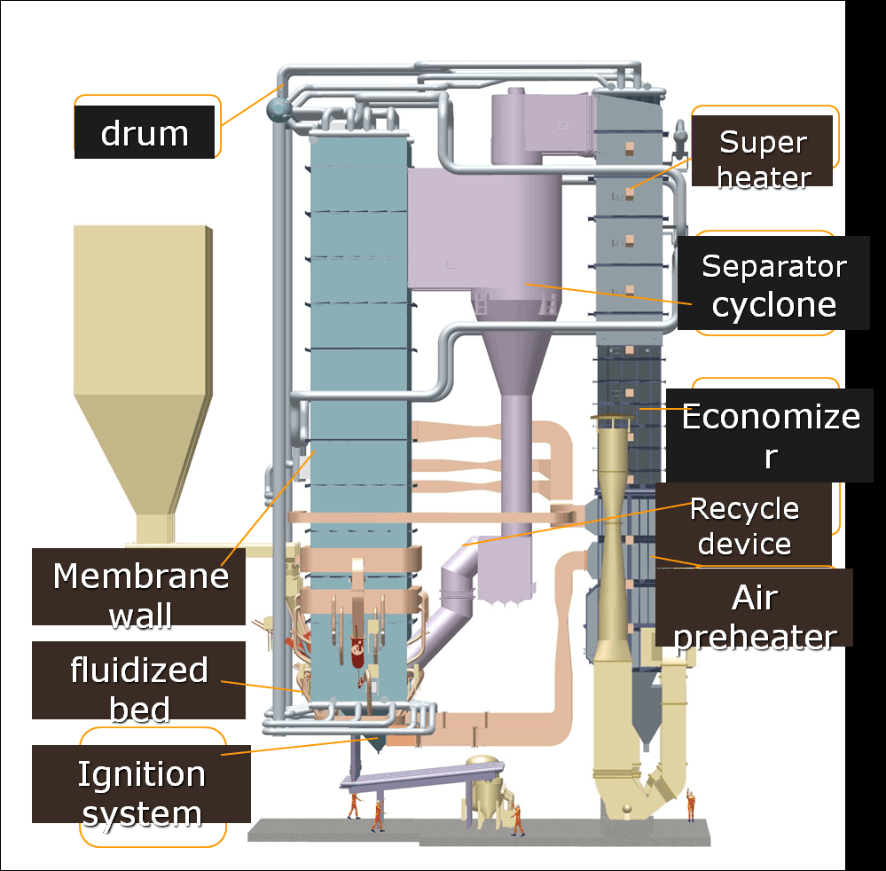
🔍 What Is Solid Circulation in a CFB Boiler?
| Component | Function |
|---|---|
| Riser (Furnace) | Combustion and vertical transport of solids |
| Cyclone Separator | Captures particles and redirects them via loop seal |
| Loop Seal | Maintains pressure balance and directs solids return |
| External Heat Exchanger (EHE) | Transfers heat from solids to steam/water system |
→ The circulation loop moves tons of hot solids every hour, carrying both ash and thermal energy.
📏 Typical Solid Circulation Rates in CFB Boilers
| Boiler Size (TPH) | Typical Circulation Rate (kg/m²·s) | Notes |
|---|---|---|
| 50–100 TPH | 20–30 | Normal for biomass and mid-size units |
| 150–250 TPH | 25–40 | Common in coal-based utility-scale boilers |
| >300 TPH | 35–50+ | High demand for external heat control |
→ The rate is often controlled via loop seal pressure, bed drain, and air velocities.
📊 Impact of Circulation Rate on Heat Transfer Zones
| Circulation Rate | Furnace Wall Heat Transfer | Superheater Performance | EHE Output | Overall Boiler Efficiency |
|---|---|---|---|---|
| Too Low | ↓ Poor wall cooling | ↓ Fluctuating temps | ↓ Limited | ↓ Efficiency drops |
| Optimal | ✅ Uniform transfer | ✅ Stable output | ✅ Maximum | ✅ High performance |
| Too High | ↑ Erosion risk | ↑ Instability risk | Overheating | May decline (damage risk) |
→ Like blood in the body, solids must flow at the right speed for thermal health.
🧪 Case Study – Adjusting Circulation Rate in a 150 TPH CFB Boiler
Initial Problem: Steam temp variation, wall tube overheating
Observation: Circulation rate ~18 kg/m²·s (too low for load demand)
Action Taken:
Increased primary air to riser
Optimized cyclone and loop seal pressure
Installed bed mass flow controller
Result:
Circulation rate increased to 32 kg/m²·s
Furnace wall temp stabilized
Steam outlet pressure stabilized
Efficiency improved from 82.1% to 87.4%
→ Proper solid movement restored heat balance across the boiler.
📈 Circulation Rate vs. Heat Transfer Coefficient
| Circulation Rate (kg/m²·s) | Average Heat Transfer Coefficient (W/m²·K) |
|---|---|
| 15 | ~200 |
| 25 | ~300 |
| 35 | ~380 |
| 45 | ~420 |
→ Each step increase in circulation improves surface heat flux—up to a safe limit.
🛠 How to Control Solid Circulation Rate
| Control Method | Purpose |
|---|---|
| Primary Air Velocity Control | Determines lift of solids into the riser |
| Loop Seal Air Adjustments | Regulates backflow and pressure drop |
| Bed Drain Flow Management | Maintains bed inventory and solids level |
| Cyclone Outlet Duct Design | Influences separation and recirculation |
| External Heat Exchanger Dampers | Balances flow through cooling zones |
→ Automation and sensor feedback help maintain stable circulation under load swings.
🔧 Problems from Improper Circulation Rates
| Problem | Caused By | Consequence |
|---|---|---|
| Erosion of Tube Surfaces | Excessive solid flow at high velocity | Reduces tube life, causes leakage |
| Temperature Instability | Irregular or low flow | Impacts turbine operation |
| Clinker Formation | Low flow leads to local overheating | Bed instability, loss of fluidization |
| Uneven Steam Superheating | Inconsistent solids in EHE | Efficiency loss, control problems |
→ Circulation must be tuned for mechanical durability and thermal performance.
🧰 Monitoring Tools for Circulation Control
| Tool / Sensor | Function |
|---|---|
| Differential Pressure Gauges | Measure bed and cyclone pressure drop |
| Thermocouples in Riser and EHE | Detect temperature uniformity |
| Mass Flow Meters for Solids | Confirm consistent circulation rate |
| SCADA with Model Predictive Control | Adjusts flow in real time |
→ Integrated controls help prevent manual guesswork and fluctuation risks.
In conclusion, the solid circulation rate in CFB boilers plays a vital role in determining how effectively heat is distributed and absorbed throughout the system. An optimized flow ensures complete combustion, uniform wall temperatures, and efficient use of external heat exchangers. Too slow or too fast—and the boiler suffers from instability, inefficiency, or damage. For CFB boilers, efficient combustion and effective heat transfer depend not just on fuel—but on how the solids move.
What Role Does Excess Air Ratio Play in Complete Combustion and Energy Loss?
Combustion in any boiler—whether firing coal, biomass, or gas—requires a precise balance of fuel and air to release energy efficiently. While a minimum amount of oxygen is needed for combustion, in real-world systems, operators provide more than the theoretical air requirement to ensure all fuel burns. This additional air is called excess air. However, too much or too little excess air can lead to major performance problems. Too little air causes incomplete combustion, resulting in carbon monoxide (CO), unburned fuel, and soot. Too much air, while preventing CO, carries valuable heat out the stack, increasing energy loss and lowering boiler efficiency. Hence, the excess air ratio plays a dual role—enabling complete combustion but also potentially causing energy waste.
The excess air ratio is critical to achieving complete combustion because it provides the oxygen needed to fully burn all fuel particles, preventing CO and soot formation. However, when excess air exceeds optimal levels, it introduces cold air into the combustion chamber, reducing flame temperature and increasing heat loss in the flue gas. Maintaining the ideal excess air ratio—typically between 10% and 20%—ensures full combustion while minimizing energy losses. Poorly controlled excess air results in either incomplete combustion or excessive heat being vented, both of which reduce efficiency.
Striking the right air-fuel balance means burning clean and saving energy.
Excess air ratio directly affects combustion completeness and energy loss in boilers.True
Optimal excess air ensures full fuel burnout, while too much or too little leads to combustion inefficiencies and thermal losses.
🔍 What Is Excess Air Ratio?
| Term | Definition |
|---|---|
| Theoretical Air | Minimum oxygen needed for complete fuel combustion |
| Excess Air | Additional air supplied above the theoretical requirement |
| Excess Air Ratio (%) | [(Actual Air – Theoretical Air) / Theoretical Air] × 100 |
→ Excess air is necessary in practical systems, but must be carefully controlled.
📏 Typical Excess Air Ranges for Fuel Types
| Fuel Type | Optimal Excess Air (%) | Flue Gas O₂ (%) | Notes |
|---|---|---|---|
| Natural Gas | 5–10 | 1–2 | Very clean combustion, low O₂ required |
| Coal (Bituminous) | 15–25 | 3.5–5 | Higher due to ash and burn variability |
| Biomass (wood) | 20–30 | 5–6 | Moisture and volatiles require higher air |
| RDF / Waste | 30–40 | 6–9 | Very variable fuel = more air needed |
→ Excess air must match the fuel’s combustion characteristics.
📊 Efficiency vs. Excess Air – The Tradeoff
| Excess Air (%) | O₂ in Flue Gas (%) | CO (ppm) | Flame Temp (°C) | Efficiency Impact |
|---|---|---|---|---|
| 0–5 | <1 | >400 | High, unstable | Incomplete combustion ↓↓ |
| 10–20 | 2–4.5 | <100 | Optimal | ✅ Maximum efficiency |
| 25–30 | 5.5–6.5 | <50 | Cooling begins | ↓ Efficiency starts dropping |
| >35 | >7 | <20 | Low | Significant stack losses ↓↓ |
→ The ideal range varies by fuel, but the sweet spot is usually 10–20% excess air.
🧪 Case Study – Biomass Boiler Efficiency vs. Excess Air
System: 12 TPH biomass-fired boiler
Initial Condition: O₂ = 7.5%, CO = 45 ppm, Stack Temp = 245°C
Efficiency = 74.1%
Optimization Actions:
Adjusted air dampers
Tuned grate speed and secondary air
Targeted O₂ = 4.2%
Results:
CO = 60 ppm
Stack Temp = 195°C
Efficiency improved to 85.8%
Fuel savings = ~1,800 tons/year
→ Lower excess air = less heat lost up the stack, higher thermal efficiency.
📈 How Excess Air Affects Energy Losses
| Flue Gas O₂ (%) | Heat Loss via Flue Gas (%) | Efficiency Drop (%) |
|---|---|---|
| 2 | ~12 | 0 |
| 4.5 | ~18 | ↓ 3–4 |
| 6.5 | ~22 | ↓ 6–8 |
| 8.5 | ~26 | ↓ 10–12 |
→ For every 1% increase in O₂, stack heat loss rises by ~1.5%.
🔧 Best Practices for Excess Air Control
| Practice | Benefit |
|---|---|
| Install O₂ Trim Control Systems | Automatically maintains ideal O₂ levels |
| Calibrate Gas Analyzers Monthly | Prevents drift and false readings |
| Perform Flue Gas Analysis | Tracks CO, O₂, NOx for combustion quality |
| Train Operators on Air-Fuel Tuning | Reduces over-airing and improves control |
| Log Efficiency vs. O₂ Trends | Identifies sweet spots for each fuel type |
→ Air control is both a technical task and an operational discipline.
🛠 Signs of Poor Excess Air Management
| Symptom | Potential Cause | Result |
|---|---|---|
| High Flue Gas Temperature | Excess air cooling the flame | Heat loss in stack |
| CO Spikes | Too little air / poor mixing | Incomplete combustion |
| Soot or Smoke | Air-starved flame | Efficiency ↓, fouling ↑ |
| Variable Steam Pressure | Instability in burn quality | Load control problems |
→ Efficient combustion needs just enough air—not too much, not too little.
In conclusion, excess air ratio is a powerful lever in boiler performance—impacting combustion quality, heat release, and energy retention. A system with too little excess air fails to burn fuel fully; one with too much throws away useful energy. The key is control: adjust air based on real-time O₂ and CO levels, matched to your fuel’s behavior. With this balance, your system runs cleaner, hotter, and more efficiently. In industrial combustion, mastering air control is mastering energy.
How Do Ash Characteristics and Fouling Impact Heat Exchanger Efficiency?
In industrial boilers—especially those using coal, biomass, or waste-derived fuels—ash generation and deposition are unavoidable. What starts as a byproduct of combustion quickly becomes a major operational burden when that ash sticks to heat exchanger surfaces. This process, called fouling, forms an insulating layer that reduces the transfer of heat from flue gases to steam or water. As this layer thickens, flue gas temperatures rise, fuel consumption increases, and thermal efficiency drops. The type of ash, its stickiness, melting point, and how it behaves at high temperature directly affect fouling severity. Left unmanaged, fouling can damage tubes, increase CO₂ emissions, and force unplanned shutdowns.
Ash characteristics and fouling impact heat exchanger efficiency by forming insulating deposits on heat transfer surfaces such as superheaters, economizers, and air preheaters. These deposits reduce thermal conductivity, increase flue gas temperature, and lower the amount of heat transferred to steam or feedwater. Sticky, low-melting-point ash causes severe fouling, especially in high-temperature zones, while dry, loose ash is easier to remove. Over time, fouling leads to reduced efficiency, increased fuel usage, and higher maintenance costs. Regular cleaning and ash control are critical to sustaining heat exchanger performance.
Ash is more than a residue—it’s a performance-determining factor in boiler systems.
Ash-related fouling significantly reduces heat exchanger efficiency in steam boilers.True
Deposited ash acts as an insulating barrier that blocks heat transfer and raises fuel consumption.
🔍 What Is Fouling and Why Does It Happen?
| Type of Fouling | Description | Common in |
|---|---|---|
| Slagging | Molten ash deposits in the furnace | High-ash coal, straw, RDF |
| Sintered Ash Fouling | Hard, fused ash on superheater surfaces | Low ash fusion temp fuels |
| Dry Ash Accumulation | Loose deposits on cooler heat exchangers | Biomass, low-temp zones |
| Corrosive Fouling | Sticky ash reacting with tube surfaces | Fuels with high Cl, Na, K |
→ Fouling location and severity depend on ash behavior at temperature.
📏 Ash Properties That Influence Fouling
| Ash Characteristic | Impact on Fouling |
|---|---|
| Fusion Temperature | Low values increase slagging and sticking risk |
| Particle Size | Fine ash travels deeper and deposits more |
| Stickiness (T250, Tfus) | Determines adhesion tendency |
| Alkali Content (Na, K) | Promotes chemical corrosion and stickiness |
| Ash Content (%) | Higher ash = more deposition potential |
| Fuel Type | Ash Content (%) | Fusion Temp (°C) | Fouling Risk |
|---|---|---|---|
| Wood Pellets | 0.5–1.5 | >1200 | Low |
| Rice Husk | 15–20 | <950 | High (silica-based) |
| Straw | 8–12 | <900 | Very High |
| Bituminous Coal | 10–25 | 1000–1150 | Moderate–High |
→ Sticky, low-melting ash is the most dangerous to efficiency.
📊 Effect of Fouling on Heat Transfer and Efficiency
| Ash Layer Thickness | Flue Gas Temp (°C) | Efficiency Loss (%) | Fuel Use Increase (%) |
|---|---|---|---|
| 0.1 mm | +10 | ~2% | ~3% |
| 0.5 mm | +30 | ~6–8% | ~7–10% |
| 1.0 mm | +50 | ≥12% | ≥15% |
→ Just half a millimeter of ash can cost thousands in fuel every month.
🧪 Case Study – Biomass Boiler Fouling Impact
System: 20 TPH biomass-fired boiler using high-ash (12%) agro-residue
Symptoms:
Flue gas temp increased from 190°C to 255°C
Steam output dropped by 8%
CO emissions increased
Diagnosis:
0.8 mm fused ash layer on superheater and economizer tubes
Pressure drop across economizer increased by 40%
Action Taken:
Offline manual cleaning
Switched to low-silica fuel mix
Installed online soot blower system
Results:
Efficiency rose from 76.4% to 85.1%
CO reduced by 60%
Steam output restored to nameplate capacity
📈 Heat Exchanger Zones Most Affected by Ash Fouling
| Component | Fouling Risk Level | Temperature Zone | Fouling Type |
|---|---|---|---|
| Superheater | Very High | 800–1000°C | Sintered ash, slag |
| Economizer | High | 250–400°C | Dry ash, ash cake |
| Air Preheater | Moderate | 150–250°C | Dusty ash, corrosion |
| Waterwall / Furnace | High | 1000–1300°C | Slagging, molten ash |
→ These surfaces require frequent inspection and cleaning strategies.
🛠 Strategies to Minimize Fouling
| Strategy | How It Helps |
|---|---|
| Fuel Blending (low-ash) | Reduces ash generation and deposition |
| Ash Modifiers (e.g., kaolin) | Raises ash melting point, reduces stickiness |
| Online Soot Blowers | Prevents buildup during operation |
| Off-line Chemical Cleaning | Removes fused ash and corrosion layers |
| Ash Behavior Testing (T250) | Predicts fouling risk and informs fuel selection |
→ Prevention and mitigation = sustained heat exchanger performance.
🔧 Monitoring Tools for Fouling Detection
| Tool/System | Measurement | Benefit |
|---|---|---|
| Flue Gas Temperature Sensors | Track rising exit gas temperature | Early fouling indicator |
| Differential Pressure Gauges | Measures blockage in economizer/APH | Tracks ash buildup |
| Boiler Efficiency Logs | Efficiency drop = possible fouling | Confirms performance loss |
| Visual Inspection (IR cameras) | Detects hot spots, ash layer growth | Identifies cleaning need |
→ Proactive monitoring prevents irreversible fouling-related damage.
In conclusion, ash characteristics and fouling behavior are critical determinants of heat exchanger efficiency in steam boilers. The nature of the ash—its quantity, stickiness, and melting point—affects where and how it accumulates. When fouling is not addressed, it creates a thermal barrier, reduces heat transfer, increases fuel demand, and shortens equipment life. To maintain optimal boiler efficiency, operators must select fuels wisely, control ash chemistry, and implement regular cleaning and monitoring. In heat exchange, clean surfaces mean efficient energy.
What Operational Practices and Maintenance Strategies Help Sustain High Efficiency?
Industrial steam boilers are critical assets in power generation, manufacturing, and thermal energy systems. However, without consistent attention to operation and maintenance, even the best-designed boiler will suffer performance degradation over time. Efficiency losses often begin subtly—through fouling, drift in control settings, fuel variability, or small leaks—and escalate into higher fuel bills, increased emissions, and reduced reliability. To sustain high thermal efficiency, plant operators must adopt proactive operational practices and structured maintenance strategies that prevent inefficiencies before they accumulate.
Sustaining high boiler efficiency requires a combination of operational practices such as precise air-fuel control, consistent combustion tuning, regular flue gas monitoring, and load optimization, along with maintenance strategies including scheduled cleaning of heat transfer surfaces, inspection of seals and gaskets, water treatment management, and calibration of key sensors. These efforts ensure optimal combustion, minimize energy losses, extend equipment life, and reduce fuel and maintenance costs.
Efficiency doesn’t just happen at startup—it must be preserved through discipline and design.
Effective operational and maintenance practices are essential to sustain high boiler efficiency.True
Without routine tuning, cleaning, and monitoring, boilers experience progressive efficiency loss due to fouling, air leaks, and combustion drift.
🔍 Key Operational Practices That Preserve Efficiency
| Practice | Purpose and Impact |
|---|---|
| Combustion Tuning | Optimizes flame stability, air-fuel ratio, and burnout |
| O₂ Trim Control Systems | Automatically adjusts air to maintain ideal excess air |
| Load Optimization | Avoids part-load inefficiency and cycling losses |
| Continuous Flue Gas Monitoring | Detects CO, O₂, and NOx variations to guide combustion tuning |
| Fuel Quality Management | Ensures stable CV, moisture, and particle size |
→ These practices form the foundation of real-time efficiency control.
📏 Performance Indicators to Track
| Indicator | Target Value / Behavior | Efficiency Insight |
|---|---|---|
| O₂ in Flue Gas (%) | 3–5% (depending on fuel) | Too high = stack loss; too low = CO ↑ |
| Flue Gas Temperature (°C) | 150–200 (after economizer) | Rising temp = fouling or air leaks |
| CO (ppm) | <100 | Indicates combustion completeness |
| Steam-to-Fuel Ratio | Should remain steady or improve | Drop signals lower efficiency |
| Stack Pressure / ΔP | Stable under load | Increased ΔP = fouling or blockage |
→ Monitoring these allows operators to respond before losses accumulate.
🛠 Routine Maintenance Strategies for Sustained Efficiency
| Maintenance Task | Frequency | Benefit to Efficiency |
|---|---|---|
| Soot Blowing / Tube Cleaning | Daily to weekly | Restores heat transfer surface performance |
| Economizer and Air Preheater Cleaning | Monthly to quarterly | Reduces flue gas temp and improves recovery |
| O₂/CO Analyzer Calibration | Monthly | Ensures accurate excess air control |
| Burner Inspection and Adjustment | Quarterly | Maintains combustion uniformity and stability |
| Feedwater Quality Checks | Weekly | Prevents scaling and corrosion |
| Insulation Integrity Inspection | Bi-annually | Prevents radiation heat loss |
| Leak Checks (steam, air, fuel) | Monthly | Avoids invisible efficiency losses |
→ Preventive maintenance is the cheapest fuel-saving investment.
📊 Efficiency Losses Without Maintenance (Typical Trends)
| Issue | Potential Efficiency Loss (%) | Root Cause |
|---|---|---|
| Fouled Superheater/Economizer | 6–10% | Missed soot blowing |
| O₂ Drift (excess air ↑) | 3–5% | Lack of combustion tuning |
| Feedwater Scaling (1 mm layer) | 2–3% | Poor water treatment |
| Damaged Insulation (5–10%) | 1–2% | Infrequent inspection |
| Steam or Air Leaks | 2–5% | Undetected pipe or gasket issues |
→ These issues can compound, causing 10–20% total efficiency drop if unmanaged.
🧪 Case Study – Maintenance-Driven Efficiency Recovery
Plant: 100 TPH coal-fired boiler
Symptoms: Rising stack temp (240°C), declining steam-to-fuel ratio
Intervention:
Offline cleaning of economizer and superheater
O₂ analyzer recalibrated (actual reading 1.8% low)
Sealed leaking steam traps and flue duct
Results:
Stack temp reduced to 185°C
O₂ maintained at 4.1%
Thermal efficiency improved from 78.2% → 86.8%
Annual coal savings: ~8,000 tons
→ Small adjustments yielded major fuel and cost savings.
🔧 Advanced Strategies for Continuous Optimization
| Advanced Practice | Description |
|---|---|
| Smart SCADA Integration | Automates alarm and trend analysis for key variables |
| Condition-Based Cleaning (ΔT, CO) | Activates soot blowing only when needed |
| Digital Twin Efficiency Modeling | Simulates optimal settings and schedules |
| Fuel Switching Protocols | Matches combustion tuning to each new fuel batch |
| Operator Efficiency KPIs | Aligns staff performance with fuel and output goals |
→ Efficiency becomes part of the daily operational culture.
📈 Efficiency Audit Checklist
| Audit Focus Area | What to Review |
|---|---|
| Combustion Performance | Burner condition, O₂/CO levels, flame behavior |
| Heat Transfer Surfaces | Visual and thermal inspection, ash deposition |
| Boiler Controls | Sensor calibration, response times, PID tuning |
| Mechanical Integrity | Valve tightness, insulation, duct leaks |
| Fuel and Air Supply | Consistency, pressure stability, flow controls |
→ A semi-annual audit prevents gradual decline from becoming major inefficiency.
In conclusion, sustaining high boiler efficiency requires both proactive operations and disciplined maintenance. Operators must continuously manage combustion, monitor key parameters, and adjust controls, while maintenance teams must ensure clean heat transfer surfaces, accurate instrumentation, and tight mechanical systems. When these efforts are systematized and supported by real-time data, the result is a reliable, efficient, and cost-effective boiler system. In industrial energy, efficiency is earned every day through precision, care, and consistency.
🔍 Conclusion
Heat transfer and combustion efficiency in CFB boilers are governed by a careful balance of operational controls, fuel properties, and fluidized bed dynamics. High efficiency is achieved not just through design, but through continuous optimization of combustion conditions, proper fuel selection, and routine maintenance of heat exchange surfaces. By managing these variables effectively, CFB boiler systems can provide consistent, low-emission, and fuel-efficient energy output, even with challenging or low-grade fuels.
📞 Contact Us
💡 Want to enhance your CFB boiler’s efficiency and fuel flexibility? Our team specializes in CFB system optimization, fuel evaluation, and combustion tuning for industrial and utility-scale applications.
🔹 Get in touch today and unlock the full efficiency potential of your CFB boiler system! 🔄🔥📈
FAQ
How does fluidization quality affect combustion efficiency in CFB boilers?
Proper fluidization ensures uniform mixing of fuel, air, and bed material, enabling complete combustion. Poor fluidization leads to uneven temperature distribution, incomplete fuel burn, and lower thermal efficiency. Maintaining the right air velocity and bed material size is key.
Why is bed temperature important for CFB boiler performance?
The optimal bed temperature (typically 800–900°C) promotes efficient combustion while minimizing NOx formation and avoiding ash agglomeration. Deviations can reduce fuel burnout efficiency and negatively affect emissions.
What role do fuel properties play in combustion efficiency?
Fuel characteristics such as calorific value, moisture content, volatile matter, and ash fusion temperature directly affect combustion. High-moisture or low-volatile fuels require longer residence times and higher excess air, reducing efficiency if not properly managed.
How does ash behavior impact heat transfer in CFB boilers?
Ash with a low melting point can cause fouling and slagging on heat exchanger surfaces, insulating them and lowering heat transfer rates. Frequent ash removal systems and additives help minimize buildup and maintain performance.
What operational strategies improve heat transfer and combustion in CFB systems?
Maintain optimal bed temperature and pressure
Use automated air distribution for precise control
Monitor and adjust fuel feed rate and particle size
Implement cyclone separators to enhance solids circulation
Ensure tube cleaning systems are active to prevent fouling
References
CFB Boiler Fundamentals and Combustion Principles – https://www.energy.gov
Heat Transfer in Fluidized Bed Boilers – https://www.sciencedirect.com
Combustion and Fluidization Dynamics – https://www.researchgate.net
CFB Boiler Operational Best Practices – https://www.bioenergyconsult.com
Effect of Fuel Properties on CFB Boiler Efficiency – https://www.mdpi.com
Ash Management in Circulating Fluidized Bed Boilers – https://www.epa.gov
Boiler Tube Fouling and Cleaning in CFBs – https://www.iea.org
Advanced Control Techniques for CFB Boilers – https://www.automation.com
CFB Heat Recovery and Efficiency Trends – https://www.energysavingtrust.org.uk
Design and Optimization of CFB Combustion Systems – https://www.asme.org